
Simple Light Detector with Sensitivity Control

A comparator circuit typically utilizes operational amplifiers (op-amps) configured to compare two input voltage levels. The output of the comparator indicates which of the two input voltages is higher. The circuit consists of two main inputs, referred to as the inverting (-) and non-inverting (+) inputs. The non-inverting input receives one voltage signal, while the inverting input receives the other.
In this specific schematic, the 1K resistors likely serve as part of a voltage divider or feedback network, which can help set reference levels or control the gain of the comparator. The output of the comparator is usually a digital signal that swings between the supply voltage levels, indicating the comparison result. If the voltage at the non-inverting input exceeds that of the inverting input, the output will transition to a high state, typically close to the positive supply voltage. Conversely, if the voltage at the inverting input is higher, the output will drop to a low state, usually near ground.
Additional components may include power supply connections, decoupling capacitors for stability, and possibly indicators such as LEDs to visually represent the output state. The schematic may also specify additional operational parameters such as input voltage ranges, output load capabilities, and response times, which are crucial for ensuring the comparator functions correctly within its intended application.The schematic diagram for the circuit is given in the picture above. Like its name suggests, a comparator compares two given voltages. The pair of 1K.. 🔗 External reference
Related Circuits
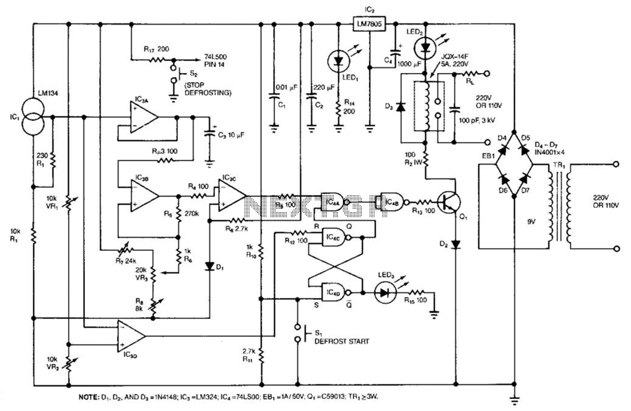
This temperature controller has a range of -50 to +150 °C and permits defrosting. R7, VR3, and R8 set the controller's trip point. SI initiates defrosting, and S2 cancels defrosting. VR1 and VR2 set the defrost temperature trip point....
This is a simple RF transmitter circuit utilizing the Holtek HT-12E encoder chip and an AM 418MHz transmitter module (WZ-X01). The use of hybrid RF transmit/receive modules simplifies the construction of the RF remote control. The transmitter can operate...
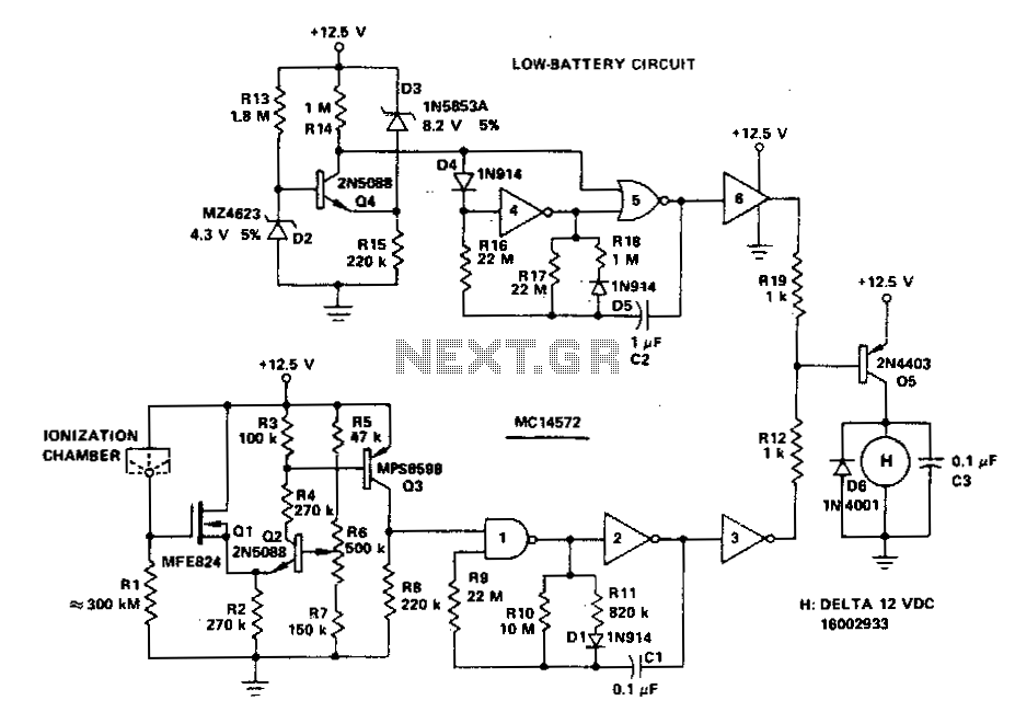
A battery-operated ionization chamber smoke detector features a circuit designed to generate a distinct alarm when the battery approaches the end of its useful life. The circuit employs the MCMOS MC14572 integrated circuit for two alarm oscillators, one for...
Involvement is a modified version of the classic circuit of automatic level control signal used in tape recorders. The purchase price of the components (using TL072) does not exceed CZK 60 for a channel. For a range of entry...
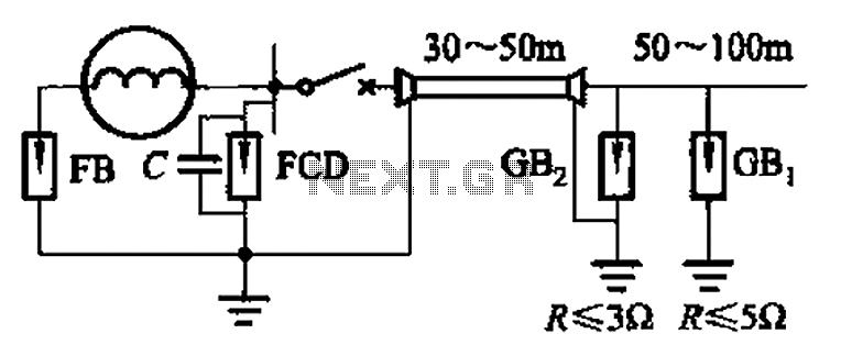
300 to 1500 kW direct distribution lightning generator designed for single capacities ranging from 300 kW to 1500 kW. The lightning generator operates within a power range of 300 kW to 1500 kW, providing a direct distribution system that facilitates...
This solar birdhouse light is an economical circuit of a mini solar lighting system. At the heart of the circuit is a mini 6V/2W solar panel, which is used to charge a 4V/800mAh rechargeable battery. The solar birdhouse light circuit...