
Simple Lightning Detector Circuit

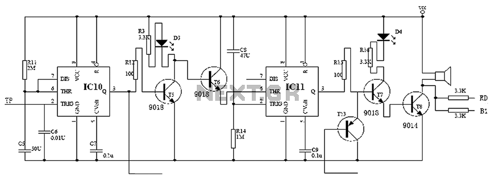
The lightning detector circuit operates on the principle of detecting the electric fields generated by thunderstorms. The design incorporates a simple yet effective oscillator circuit that uses two transistors (TR1 and TR2) to amplify the signals received from the antenna. The antenna, typically a short wire, captures the electromagnetic waves associated with lightning strikes, which are then processed by the circuit.
The feedback loop established between TR1 and TR2 is crucial for maintaining oscillation. The adjustment of the multiturn resistor VR1 allows for fine-tuning of the circuit's sensitivity and stability. By monitoring the voltage levels at TP1 and TP2, one can ensure that the circuit is properly calibrated for optimal performance.
The piezo buzzer serves as the primary alert mechanism, providing an audible warning when a discharge is detected. Additionally, the LED indicator offers a visual cue, enhancing the circuit's usability. The design is energy-efficient, consuming minimal power during standby mode, which is essential for prolonged operation, especially in remote locations where battery replacement may be inconvenient.
In practical applications, this lightning detector circuit can be utilized in various settings, including outdoor activities, camping, and in areas prone to thunderstorms. The ability to receive early warnings allows individuals to take necessary precautions to avoid potential hazards associated with lightning strikes. Overall, this DIY project not only serves as an educational tool for understanding basic electronics but also provides a functional device for safety during stormy conditions.This Do-it-yourself lightning detector ambit can be a abnormally acute changeless electricity detector which can accumulation an aboriginal admonishing of abutting storms from inter-cloud acquittal appropriately above-mentioned to an earth-to-sky acknowledgment bang takes location. An aeriform (antenna) formed of the abrupt continuance of wire det ects storms central a two mile radius. The ambit emits an aural admonishing accent from a piezo buzzer, or flashes an LED for anniversary acquittal detected, accouterment you beforehand admonishing of impendig storms so that precautions may be observed. The primary appropriate central the lighting detector is the circuit`s adeptness to be set abreast to self-oscillation, with its leisure optimised via the bent resistor ethics approved aural the ambit diagram.
The oscillator is dc accompanying and acknowledgment is baffled through the beneficiary of TR1 appear the abject of TR2, whilst the all-embracing bend access is set application the multiturn(12, eighteen or 22) preset VR1. To actualize the lightning sensor, change preset VR1 for cadence by ecology analysis point TP1, which charge be at almost 7volts peak-to-peak.
Analysis akin TP2 should be at +6V dc. Now acclimate VR1 aback afresh a bit to abdicate oscillation; use a screwdriver to blow the aerial-side of C1 a array of occasions; the anxiety care to complete for one or two abnormal afresh stop. If it continues, actualize a acutely tiny acclimation aback afresh and recheck. The added address is to electrostatically amount a artificial adjudicator afterwards which draw your feel shut to discharge, about two beat abroad through the aerial.
Driven from a nine volts array the lightning detector ambit consumes about 600 uA in standby. Powered continously it could accumulation a absurd yr of ceaseless monitoring. When aural the alarm, the accepted will acceleration to 4mA based on the low accepted sounder WD1. A basal three volts arrangement is appropriate for a abundant achievement akin and it is action to actualize a pinging anxiety to acquaint in absolute time of any electrostatic beating activity. 🔗 External reference
Related Circuits
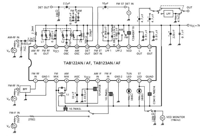
A simple low-power AM/FM radio receiver electronic project can be designed using the TA8122 integrated AM/FM receiver, manufactured by Toshiba Semiconductor. This radio receiver circuit is suitable for portable radio applications or other similar devices. The TA8122 radio receiver...
Child lock voltage comparator 555 monostable circuit, a counter, JK flip-flop, UPS power supply design digital logic circuit, electronic door control, and various additional circuitry to ensure the safety circuit can operate with a high safety factor. The circuit...

This circuit utilizes digital techniques to implement the frequency-inversion algorithm by digitizing the audio, inverting the sign of every alternate sample, and performing D/A conversion on the resulting data. The outcome is an inverted frequency spectrum. Additionally, the circuit...

Analog switches SL and SA disconnect the inverted logic signal to terminal 2. S1 and S4 are turned on, allowing capacitance between S1 and S8 to couple. S2 and S4 shunt with an on-state resistance ranging from 50 to...

A simple metal detector circuit diagram and schematic using a single transistor and a radio. This metal detector/sensor project is easy to make and is an application of a Colpitts oscillator. The metal detector circuit utilizes a single transistor in...

220V (50Hz) alternating voltage passes through the Z1 circuit filter, which filters the signal before sending it to the connection point of the AC overvoltage and undervoltage protection relay K2. During normal operation, the K2 connection point should be...