
Simple Metal Detector DIY
The described circuit functions as a basic metal detector utilizing the CS209A integrated circuit. The CS209A serves as the core component, featuring an oscillator that generates a frequency based on the characteristics of an LC (inductor-capacitor) circuit. In this application, the inductor is represented by a coil with an inductance value of 100 microhenries (uH).
When the coil is positioned near metallic objects, the inductance of the coil changes due to the presence of the metal, which alters the oscillation frequency of the circuit. This change in frequency is detected by the CS209A, which subsequently activates an LED (LED 1) and a buzzer. The LED provides a visual indication of metal detection, while the buzzer offers an audible alert.
The circuit includes a variable resistor (VR1) that allows for adjustment of the sensitivity of the metal detector. Initially, VR1 should be set to a position where the LED lights up and the buzzer sounds when the coil is away from any metal objects. This ensures that the circuit is responsive to changes in inductance. After this initial setup, VR1 can be fine-tuned to a point where both the LED and the buzzer are inactive, indicating that the circuit is calibrated to detect metal objects effectively without false positives from environmental interference.
The simplicity of this circuit makes it suitable for DIY projects and educational purposes, demonstrating fundamental principles of inductance, oscillation, and detection in electronics. Proper assembly and calibration of the components are crucial for optimal performance and reliability of the metal detector.LED 1 will light and the buzzer turns on when the coil is changing inductance. The setup is easy, VR1 is adjusted ( away from any metal objects ) so that LED 1 will light and the buzzor sounds on, and then VR1 will be trimmed until led and buzzer are off. The heart of this diy metal detector circuit is CS209A. The metal detector it is build with one coil of 100uH. CS209A has one oscillator wich forms an LC circuit, the inductance of the coil will change when it is near metal objects. 🔗 External reference
Related Circuits
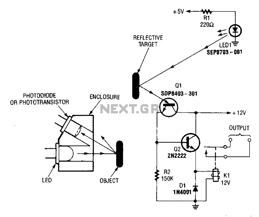
A reflex isolator detects the presence of an object by reflecting light from the object back to the sensor. This technique is effective when an object is in close proximity to the sensor. Reflex isolators, also known as proximity sensors,...
This circuit is designed to detect incoming calls on a cellular phone, even when the phone's ringer is turned off, by utilizing a flashing LED indicator. The device should be positioned a few centimeters away from the cellular phone,...

A circuit breaker is an electronic device that functions to protect an electrical circuit from hazards or damage caused by overloads or short circuits. A circuit breaker operates by automatically interrupting the flow of electricity when it detects an...
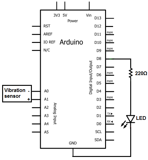
The sensors consist of a thin strip of piezoelectric material with a rivet at one end acting as a weight. When vibration occurs, the weight moves, stressing the piezo material, which generates a spike in voltage that can reach...

All components used in the Moving Sensor/Detector Schematic Diagram utilize the IC NE555 and the Phototransistor L14F. The primary component in this circuit is the IC NE555, along with an IR LED, the Phototransistor L14F, and the IC LM1458....

The experimenter's pot is a solid state potentiometer using Dallas semiconductor's DS1869 and National's LM78L05, two electrolytic capacitors, two small push button switches, and two optional Molex connectors. This project is very useful, especially in finding the right value...