
Cellular Phone Calling Detector Circuit

The circuit operates based on the principle of electromagnetic induction, where the sensor coil L1 detects the electromagnetic field produced by the cellular phone when it receives a call. The coil is designed to be sensitive enough to pick up the field without requiring direct contact with the phone.
The main components of the circuit include the sensor coil L1, a rectifier circuit to convert the alternating current (AC) induced in the coil to direct current (DC), and a microcontroller or a simple transistor-based circuit to drive the LED. The LED serves as a visual indicator of an incoming call, flashing in response to the detected signal.
To enhance the circuit's performance, the sensor coil can be tuned to a specific frequency range that corresponds to the typical operating frequencies of cellular phones. This may involve adjusting the number of turns in the coil or incorporating capacitive elements to create a resonant circuit.
In terms of power supply, the circuit can be powered by a small battery or a low-voltage power source, ensuring that it remains portable and easy to use. The entire assembly can be housed in a small enclosure that allows for easy placement near the cellular phone without obstructing its normal operation.
Overall, this circuit provides a practical solution for individuals who may need to be alerted to incoming calls discreetly, without relying on the phone's built-in ringer.This circuit was designed to detect when a call is incoming in a cellular phone (even when the calling tone of the device is switched-off) by means of a flashing LED. The device must be placed a few centimeters from the cellular phone, so its sensor coil L1 can detect the field emitted by the phone receiver during an incoming call..
🔗 External reference
Related Circuits

A 5V power supply using IC 7805 is designed and explained with a neat circuit diagram. The circuit for a 5V power supply utilizing the IC 7805 voltage regulator is a straightforward and efficient design that provides a stable output...
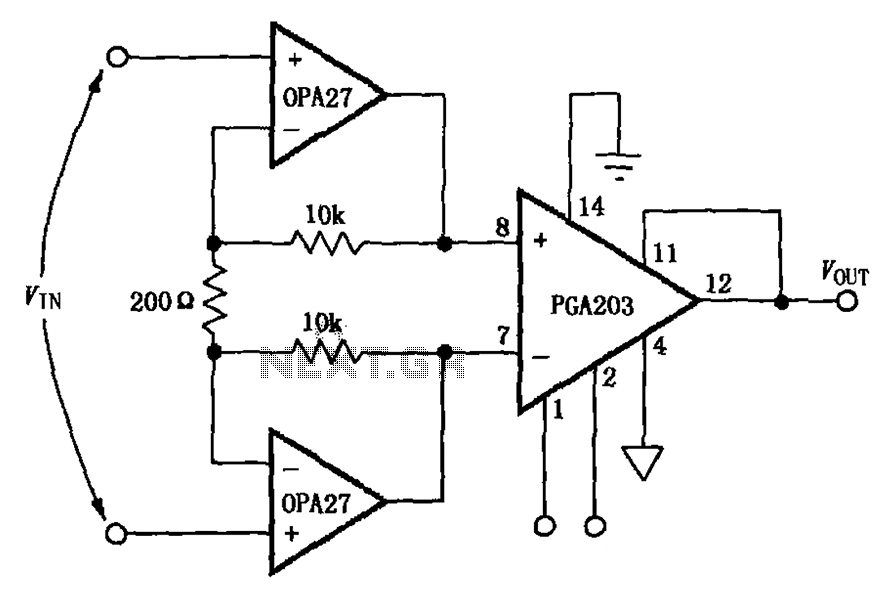
The circuit depicted in the figure features a PGA203 operational amplifier (op amp) and two OPA27 op amps, forming a low-noise differential amplifier. The input stage utilizes the PGA203 in conjunction with the two OPA27 op amps. The non-inverting...
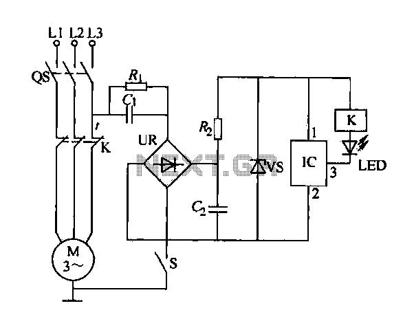
The electric sewing machine saving circuit is designed with a Hall switch integrated circuit (IC) and a relay (K). When the switch is closed, power is activated. The circuit includes a resistor (R) and a capacitor (Ci) for RC...

This circuit produces a soft turn-on for halogen lamp filaments upon powering up. The MOSFET used is a BUZ10, which has a resistance of 0.2 ohms. Resistors R1, R2, and capacitor C1 set the turn-on rate, while diode D1...
Face Through attendance is the world's first embedded facial recognition machine, with an error rate of less than one in one hundred thousand and a rejection rate of less than one percent. In the field of biometrics, this device...
Sometimes when experimenting with different soundcards and MIDI interfaces it is useful to see if there is some data going in MIDI interface. This can be easily tested with this adapter, which converts the midi signals to visible light...