
Simple Pulse Generator

Pulse generators are versatile instruments used in various applications, including testing electronic components, simulating signal conditions, and generating precise timing signals. A typical pulse generator circuit consists of several key components: a clock oscillator, pulse shaping circuitry, and output stages. The clock oscillator generates a stable frequency signal, which can be adjusted to set the pulse repetition rate.
The pulse shaping circuitry is crucial for controlling the characteristics of the output pulses, such as rise time, fall time, and pulse width. This circuitry may include analog components like resistors, capacitors, and operational amplifiers, as well as digital components such as microcontrollers or field-programmable gate arrays (FPGAs) for precise digital control.
The output stage of the pulse generator is responsible for delivering the generated pulses to the load. This stage may include transistors or operational amplifiers configured to provide the necessary drive capability to meet the load requirements. Additionally, features like variable amplitude control and external triggering can be implemented to enhance the functionality of the pulse generator.
In more advanced pulse generators, multiple output channels can be integrated, allowing for simultaneous generation of different pulse characteristics. Each channel can be independently configured for parameters such as pulse width, delay, and amplitude, making these devices suitable for complex testing scenarios where multiple signal conditions need to be simulated.
Moreover, pulse generators with digital delay capabilities can provide high precision and flexibility, enabling users to create complex timing sequences and patterns. The integration of digital techniques with analog components allows for enhanced performance, making modern pulse generators indispensable tools in electronic testing and development environments.A Pulse generator usually allows control of the pulse repetition rate, pulse width, pulse delay and pulse amplitude. More sophisticated pulse generators may allow control over the rise time and fall time of the pulses.
A pulse generator`s delay is measured with respect to an internal or external trigger. The pulse generator`s rate may be determine d by a frequency or period adjust (rep rate). Pulse generators may use digital techniques, analog techniques, or a combination of both techniques to form the output pulses. For example, the pulse repetition rate and duration may be digitally controlled but the pulse amplitude and rise and fall times may be determined by analog circuitry in the output stage of the pulse generator.
With correct adjustment, a pulse generator can also produce a 50% duty cycle square wave. Pulse generators are generally single-channel providing one frequency, delay, width and output. To produce multiple pulses, these simple pulse generators would have to be ganged in series or in parallel. Some Pulse Generators like the BNC Model DB-2 Random pulse generator simulate actual operating conditions without requiring a live source and detector combination.
Such parameters as frequency response, linearity, and discrimination levels may easily be measured without the inconvenience of dim oscilloscope display or long accumulation times by a pulse generator. Proper operation of baseline restorer circuits may be quickly verified. Scalers and ratemeters may be checked for satisfactory pulse recognition under random pulse (each pulse generator may be equipped with different capabilities and features).
The negligible amplitude shift with frequency of the pulser (pulse generator) makes the standard frequency test using a live source and a low rate precision pulse generator unnecessary. Although most test applications will find the pulser connected to the test input of a charge sensitive preamplifier, it is possible to simulate the preamp itself with the pulse generator.
The pulser is connected directly to the main amplifier and the preamp decay time constant is matched by proper selection of the pulser fall time. Set up of a system containing an inaccessible preamp can then be accomplished with ease. For accurate simulation of detector pulse shapes, the rise time control should be adjusted to match 2.
2 times the detector decay time constant. For example, if a pulse shape analyzer working with CsI-NaI phoswich is to be tested, the pulse generator rise time should be set to 0. 5 µsec rise time for the NaI signal, and 2 µsec for the CsI signal. Intermediate signals are best obtained by mixing the outputs from two synchronized generators, 2 µsec rise time.
By varying the amplitude ratio of the two generators, intermediate values of rise time are generated. Solid state and plastic detectors have decay constants far shorter than the adjustment range of this generator.
However, the shaping time constants used in virtually all systems are greater than the 100 nsec minimum rise time. The ballistic deficit formula predicts the reduction in amplitude, B. D. , for a shaping system containing identical time constants for all shaping. The external reference allows remote programming of the amplitude of the pulser, and the external trigger permits control of the output pulse rate.
The latter provision is especially convenient if the average random rate needs to be controlled and an external random clock is unavailable. By placing the pulser in the random mode, a periodic waveform at the external trigger input will control the average random rate.
A new family of pulse generators can produce multiple-channels of independent widths and delays and independent outputs and polarities. Often called digital delay/pulse generators, the newest designs even offer differing repetition rates with each channel, differing delays and differing widths.
They can be producing timing signals and operate in output modes independent of the other channels. 🔗 External reference
Related Circuits
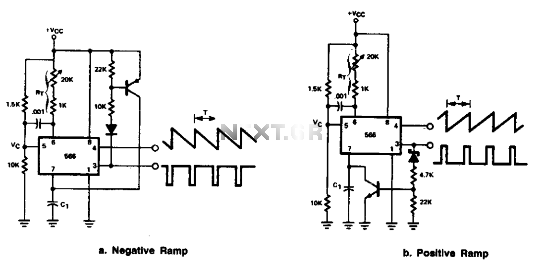
The 566 can be configured as either a positive or negative ramp generator. In the positive ramp generator configuration, the external transistor controlled by the output at Pin 3 quickly discharges capacitor C1 at the conclusion of the charging...
The circuit shown above can be used to control a unipolar stepper motor which has FOUR coils. The above circuit can be for a motor current of up to about 500mA per winding with suitable heat sinks for the...
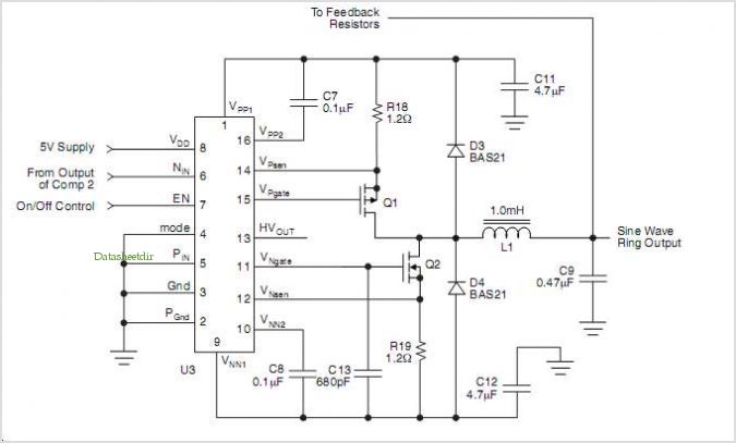
The HV739 is a monolithic single-channel, high-speed, high-voltage ultrasound transmitter pulser. This integrated, high-performance circuit is housed in a single 5x5 mm, 32-lead QFN package. The HV739 can deliver up to ±3.0 A of source and sink current to...
This is a simple sawtooth generator circuit. The advantages of this circuit include low cost and the ability to produce an auxiliary square wave at the same frequency. This circuit can be utilized to sweep the frequency of another...
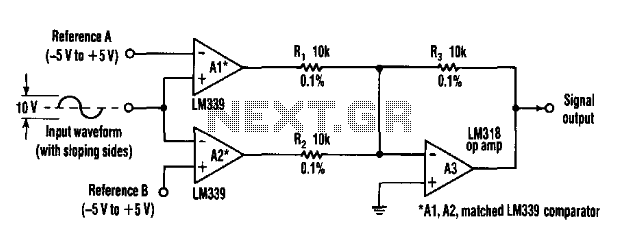
This circuit can extract harmonics from various waveforms. With a sloped input waveform, the comparator produces a pulse width that is proportional to a reference plus input amplitude. As the pulse width changes, the harmonics spectrum changes. Combining the...
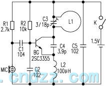
The loop antenna L1 is utilized for emission and also functions as the oscillation coil. The high-frequency current flowing through the antenna is synchronized in resonance with the oscillation frequency, ensuring optimal emission performance. Practical applications indicate that the...