
simple pwm boost converter io disconnect solves malfunctions

A PWM (Pulse Width Modulation) boost converter is an essential component in power electronics, designed to step up a lower input voltage (VIN) to a higher output voltage (VOUT) while maintaining high efficiency. The operation of this converter relies on the control of the duty cycle of the switching element, typically a transistor, to regulate the output voltage.
The circuit typically consists of several key components: an inductor, a switch (transistor), a diode, and a capacitor. The inductor stores energy when the switch is closed and releases it to the output when the switch is open. The PWM controller adjusts the duty cycle of the switch to control the amount of energy transferred to the output, ensuring that VOUT remains stable despite variations in VIN or load conditions.
The DC path from VIN to VOUT implies that there is a direct electrical connection between the input and output, which is crucial for maintaining efficiency during the conversion process. This connection allows for minimal energy loss, as the converter can directly transfer the input voltage to the output when the switch is in the appropriate state.
In summary, a PWM boost converter is a vital circuit for applications requiring voltage step-up with high efficiency, leveraging a simple controller to manage the power conversion process effectively.A PWM boost converter in a simple controller has a DC path from input VIN to VOUT, which is utilized for high-efficiency power conversion.. 🔗 External reference
Related Circuits
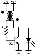
Previously, a boost circuit was tested that enables the powering of a 3 V LED using a discharged battery (approximately 1 V or lower). This circuit consists of a single transistor, one resistor, and a small transformer with a...
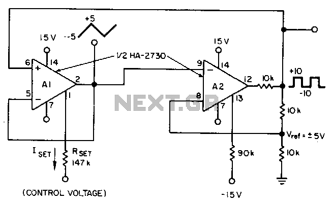
This circuit utilizes a programmable operational amplifier, specifically the HA2730, which is a two-amplifier monolithic chip featuring independent programming ports for each amplifier. The parameters of the amplifiers, including the slew rate, vary linearly based on a set current....
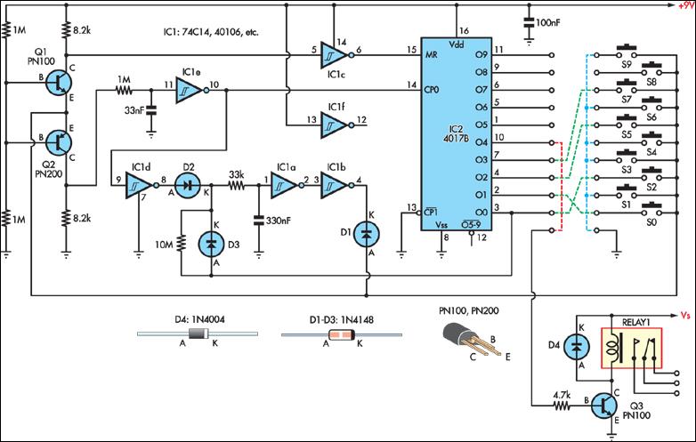
This simple combination lock accommodates codes from 1 to 9 digits long, with the only restriction being that the same digit cannot be used twice. The circuit is designed for a 4-digit code, illustrated by the example "2057". Any...
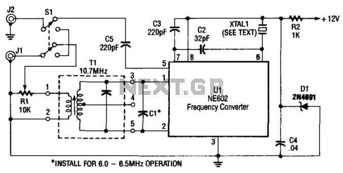
A Signetics NE602 is utilized in this converter to tune the frequency range of 9.5 to 9.8 MHz. An AM car radio functions as a tunable intermediate frequency (IF) amplifier, with the output being taken from J2, the auto...

The pressure transmitter circuit data acquisition system utilizes the 1B31, an 18-bit A/D converter (AD1170), and an MCS-51 microcontroller. The configuration, as depicted in the accompanying diagram, features a full-scale output voltage of 10 mV from the pressure transmitter...
This characterization circuit, along with a PC and specific software, accurately measures the complete discharge cycle of a rechargeable AA cell. The capacity and output resistance of the cell can be easily determined from the resulting curve of these...