
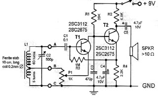
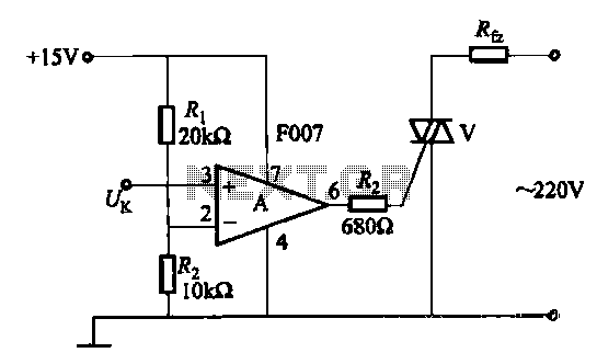
Simple Radio Circuit using Op Amp

The presented radio circuit schematic utilizes an operational amplifier (op-amp) to create a cost-effective and straightforward radio receiver. The core functionality of the circuit revolves around the op-amp, which serves as a sensitive audio amplifier, capable of amplifying incoming radio frequency (RF) signals.
The circuit typically includes several key components: the op-amp itself, resistors, capacitors, and possibly an inductor or transformer for tuning purposes. The input stage of the circuit is designed to capture RF signals from an antenna. The antenna can be a simple wire or a more sophisticated design, depending on the required range and sensitivity.
In the circuit, the op-amp is configured in a non-inverting amplifier configuration, which allows for high input impedance and low output impedance, making it ideal for signal amplification. The gain of the amplifier can be adjusted by changing the feedback resistor values, which allows for flexibility in handling varying signal strengths.
Capacitors are used in the circuit to filter out unwanted frequencies and noise, ensuring that only the desired audio frequency signals are amplified. Additionally, a tuning circuit may be incorporated using an inductor and variable capacitor to allow the user to select specific radio stations by adjusting the resonant frequency of the circuit.
Overall, this low-cost radio circuit schematic is an excellent project for beginners in electronics, providing hands-on experience with op-amps and basic radio technology while demonstrating fundamental principles of signal amplification and tuning.A low cost,simple radio circuit schematic using op amp.This radio circuit diagram consists of a sensitive audio amplifier which receives strong signals.. 🔗 External reference
Related Circuits
This circuit is a simple one-transistor Audion type radio powered by a 1.5 V battery. It utilizes a pair of standard low-impedance headphones, wired in series to achieve a total impedance of 64 ohms. The power supply to the...
For some time, a variety of tape cassette decks have been available at low prices from mail order businesses and electronics retailers. These decks do not contain any electronics. Building a recording amplifier and the fairly complex magnetic biasing...
This current-limiting circuit, illustrated in this example as part of a small bench power supply, could theoretically be utilized alongside any dual-rail current source. The section of the circuit to the left of the diagram restricts the input current...
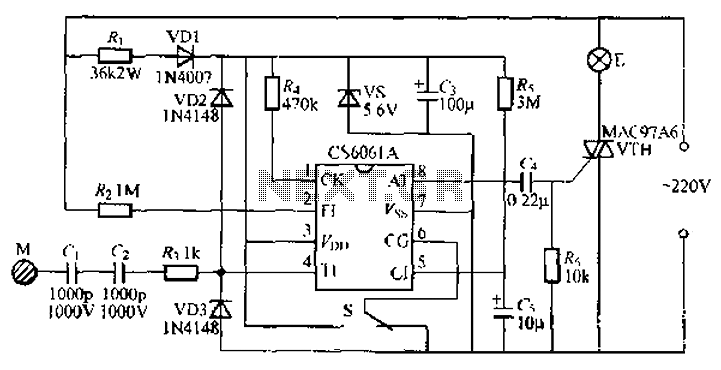
The CS6061A integrated circuit is designed for touch-step dimming lights. It features a two-state female switching function and is reliable, capable of adapting to long cables and larger touch-sensitive pad loads (400pF). The collector circuit of the CS6061A utilizes...
A transistor optocoupler interface circuit, as described in section 15.1.6, has been implemented. This circuit serves as a transistor interface with other circuits. The transistor optocoupler interface circuit utilizes a light-emitting diode (LED) and a phototransistor to achieve electrical isolation...
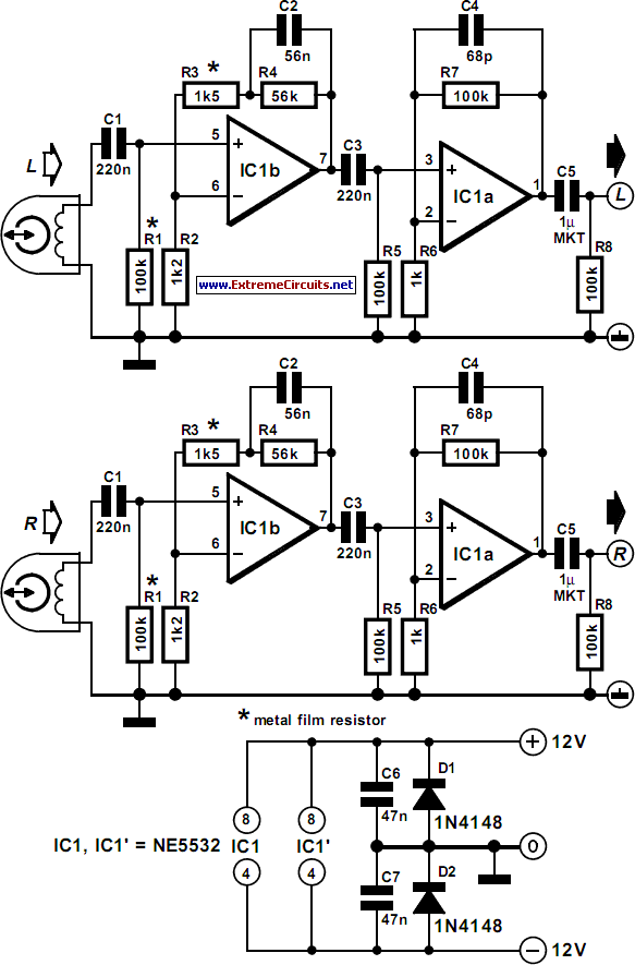
The function of this automatic volume control circuit is to amplify signals without distorting their dynamic compression. The amplitude differences in the signal are leveled off, eliminating disturbing effects. This technique avoids overcompensation in volume. The circuit is utilized...