
Thyristor interface circuit operational amplifier

The transistor optocoupler interface circuit utilizes a light-emitting diode (LED) and a phototransistor to achieve electrical isolation between different parts of a system while allowing signal transmission. The LED emits light when current flows through it, and this light is detected by the phototransistor, which then allows current to flow in its circuit, effectively transferring the signal.
In this implementation, the circuit typically consists of an input stage that includes a resistor connected to the LED, which limits the current to a safe level. The LED is connected in series with the input signal source, ensuring that when the input signal is high, the LED turns on, emitting light. The phototransistor is positioned in proximity to the LED, with its collector and emitter configured to control the output circuit.
The output side may include additional components such as pull-up resistors to ensure proper voltage levels when the phototransistor is in the off state. This arrangement helps maintain the integrity of the signal and prevents noise from affecting the output.
The transistor interface circuit is particularly useful in applications where electrical isolation is necessary, such as in power electronics, microcontroller interfacing, and communication systems. It provides a reliable means of interfacing between different voltage levels and protecting sensitive components from high voltages or spikes that may occur in the system.
Careful selection of the LED and phototransistor parameters, including their forward current, reverse voltage, and switching speed, is crucial to ensure optimal performance of the optocoupler circuit in its intended application.Transistor optocouplers interface circuit as described in 15.1.6 has been. Transistor interface circuit with other circuit
Related Circuits

This is a beta release schematic. Use at your own risk. The idea is to add this circuitry to a board that already has RAM at address 2000 and an 82C55 I/O chip to provide ports A, B, and...
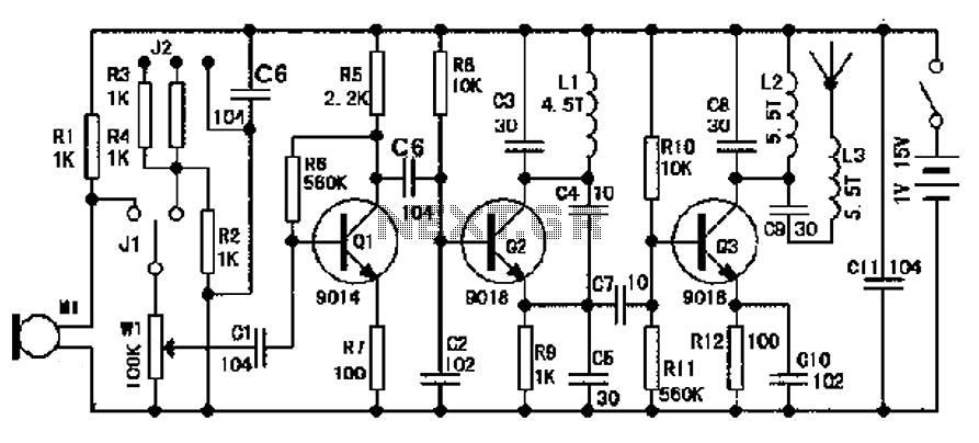
The design of an FM radio transmission frequency band enables compatibility with any FM radio receiver, allowing the high-frequency signal to be transmitted and restored from an audio signal. This technology serves various applications. Applications of a wireless microphone...

The principle of the dancing blanket is straightforward; it functions as a direct retrofit for a keyboard or gamepad. Each key on the keyboard and gamepad operates as a switch, which connects to the ground through a wire lead....

This document presents a circuit example for interfacing an RF module using the HT12E/D encoder-decoder pair. The attached circuit can be utilized for data transmission via the RF module, which is designed for single-channel operation, allowing only serial data...
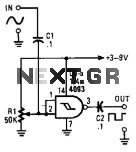
This circuit converts a sine wave into a square wave. It consists of a single 2-input NAND Schmitt trigger configured as an inverter, with an adjustable trigger level at its input. As the input voltage exceeds the gate's trigger...
The primary components of this doorbell circuit include two NE555 timer integrated circuits (ICs). When the switch S1 is pressed momentarily, the loudspeaker emits a bell tone for the duration determined by the time period of the monostable multivibrator...