
Simple Ring Modulator

To begin assembly, cut the terminal strip into two pieces of two terminals and two pieces of three terminals. The four diodes can be positioned correctly by trimming the leads to appropriate lengths and securing them under the screws in the terminal blocks. The leads of the diodes may be folded back slightly to ensure they are trapped securely. It is important not to tighten the screws excessively at this stage to allow for potential adjustments. A small length of PVC insulation is included to prevent one of the diagonally mounted diodes from shorting against another.
Next, connect the two transformers similarly. The transformer sides with three wires should be connected to the three-way terminal blocks with the diodes, while the side with two wires connects to a separate two-way block. Carefully strip the wires on the jack plug leads by scoring around the outer PVC and the inner core to expose the copper wire. Twist the bare wires and fold them back to facilitate secure connections under the screws. Connect the wires as follows: one to the two terminals on the left, another to the two terminals on the right, and the final lead to the two center terminals. The white-cored wire corresponds to the left audio channel.
Once all connections are confirmed, tighten the terminal screws to secure the assembly. The three plugs are labeled A, B, and C. Plug C serves as the output from the circuit, which should connect to computer speakers or a line input on an amplifier with speakers or headphones. Plug A is designated as the voice input, which should be connected to the headphone or line output of an MP3 player containing the voice signal to be processed. In cases where a portable recording device with a microphone is used, the microphone signal may be amplified and played through the headphones during recording, allowing for live use of the system. Plug B should be connected to another MP3 player or similar device that plays back a 30Hz sine wave signal. Links to MP3 and WAV versions of 30Hz tones are provided for convenience. If an electronic signal generator is available, it can also be utilized for this purpose.
This ring modulator circuit offers a unique opportunity to explore sound synthesis and effects generation, making it an engaging project for audio enthusiasts and electronics hobbyists alike.This is a very simple ring modulator circuit which will allow you to make interesting analogue sound effects using two audio sources and some kind of amplifier or recording device. Almost everyone has access to a couple of mp3 players and some powered computer speakers nowadays, so this is quite an easy way to go about it.
One very familiar use fo r this old style of ring mod is that which produces the "Dalek" voice. I will concentrate on that application in the text, but there are other effects you can produce which I`ll discuss later. I supply a kit of all the electronic parts in the list above, or you can buy your own. I`ve assumed that you have a small screwdriver for the terminal screws, some small wire cutters for trimming the component leads and some means of stripping the insulation from the wire.
A craft knife is good for that. It is best to mount up the circuit in an enclosure or nail it down to some wood when it is all working, and the holes in the terminal strips make that easy to do. This is a nice simple circuit which you can make pretty much just by looking at the final picture. The components list has links to photographs of the components. I`ve included a full electronic explanation later on. If that doesn`t make any sense, don`t let it put you off just building the circuit. Using a craft knife or scissors, cut the terminal strip into two pieces of two terminals and two pieces of three terminals.
The four diodes can then be assembled the correct way around by cutting the leads to about the right length and trapping the ends under the screws in the terminal blocks as shown. I fold the leads of the diodes back a bit at the end to make them easier to trap properly under the terminal screws.
Don`t tighten the screws too much at this stage as you may want to re-adjust the assembly. There is a small length of PVC insulation provided which can be put on the leads of one of the diagonally mounted diodes. This avoids it shorting against the other one. You should now have something that looks like this: Next connect the two transformers in a similar way.
The transformer sides with the three wires go into the three-way terminal blocks with the diodes, and the side with the two wires connects into another two-way block. Next, strip the wires on the jack plug leads by carefully scoring round the outer PVC and then the inner core and baring the copper wire as shown.
Twist the bare wires and fold them back at the ends to make them easier to trap properly under the screws. Then connect them up as shown, one to the two terminals on the left, another to the two terminals on the right, and the final lead to the two centre terminals in the middle.
I have used the white cored wire and this corresponds to the left channel. This is a pretty simple project and if you`re sure everything is in the right place, you can screw down the terminals a bit tighter and make sure that everything is secure. I`ve labelled the three plugs A, B and C. C is the output from this circuit and that needs to plug into some computer speakers, or a line input to an amplifier with some speakers or headphones.
I`m going to call C just the "output. " A is the input which has the voice signal fed into it. This needs to connect to the headphone output or line output of some mp3 player which has the voice signal to be processed on it. If you have a portable recording device with a microphone, you may well find that the signal from the microphone is amplified and played out of the headphones while recording.
In that case you can use that as a microphone amplifier and use the system live, speaking into the microphone. I`m going to call A the "voice input. " B is the input which needs to be connected to another mp3 player or similar device which is going to play back a 30Hz sine wave signal.
There are links to mp3 and wav versions of 30Hz tones shown below. If you have an electronic signal generator you 🔗 External reference
Related Circuits
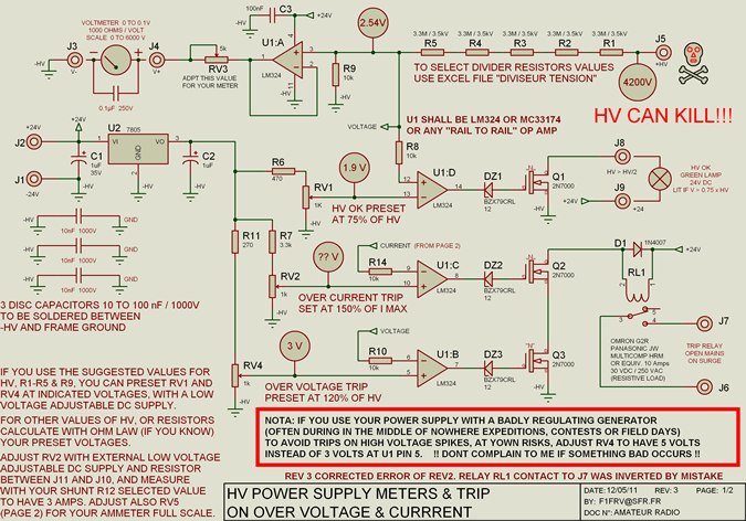
High voltage resistors for the high voltage divider are SFERNICE or PHILIPS type VR37 (3.5 kV - 0.4 W). They are not expensive (even if they are sold in quantities of 25 or 50 units), and it is always...
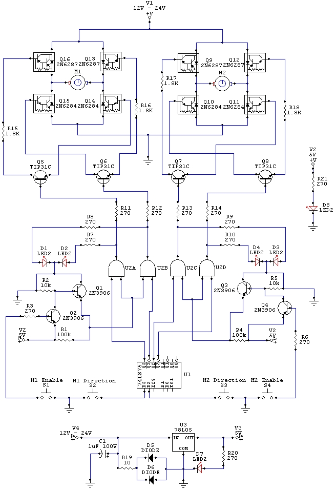
The wiring schematic played a significant role in the robot. This diagram is used to graphically display all the wiring of the motor-controlling micro-components that enabled the robot to physically move forward, backward, left, right, and stop. This diagram...
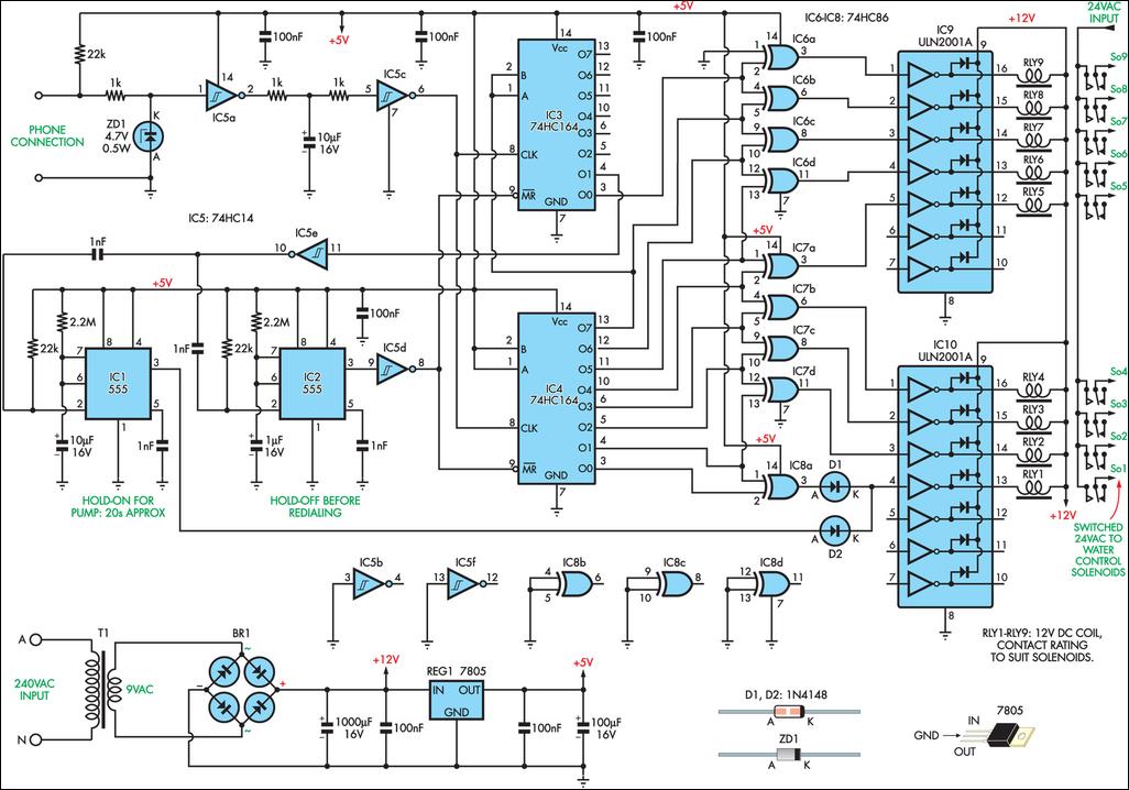
This remotely controlled watering system is cost-effective and easily expandable. It operates in conjunction with a conventional watering timer, enabling remote switching between nine zones. The prototype is designed for use with a bore system, where a deep-well pump...
1996 Isuzu Rodeo Headlight Wiring Diagram. The 1996 Isuzu Rodeo headlight wiring diagram provides a detailed representation of the electrical connections and components involved in the vehicle's headlight system. This diagram is essential for understanding how the headlight assembly operates...

This circuit is designed to charge between one and twelve NiCd cells using a car battery. With switch S1 set to the normal position, it is capable of charging up to six cells. The circuit operates by utilizing a car...
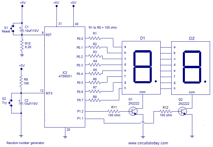
A simple random number generator utilizing the 8051 microcontroller. The AT89S51 is the controller employed in this setup. The circuit design for the random number generator based on the AT89S51 microcontroller involves several essential components and connections. The AT89S51 microcontroller,...