
HV SUPPLY METERING & OVERVOLTAGE TRIP

High voltage resistors, such as the SFERNICE or PHILIPS type VR37, are critical components in constructing a high voltage divider. With a voltage rating of 3.5 kV and a power rating of 0.4 W, these resistors facilitate the safe division of high voltage levels for various applications. Their affordability, even when purchased in bulk, makes them a practical choice for hobbyists and professionals alike.
The design of the power command circuit is essential for ensuring operational safety and reliability. It integrates push buttons and an auto-maintain loop, which allows for consistent operation of the mains power relay. The inclusion of a "soft start" feature in the power supply schematic is particularly beneficial as it mitigates inrush currents that can damage components during startup.
For accurate measurement and calibration, meter scales can be developed using available software tools like F5BU's GALVA and WB6BLD's meter software, providing flexibility in design and functionality. Additional resources, such as downloadable files for PCB layout, bills of materials, and datasheets, enhance the ease of assembly and ensure that all necessary components are accounted for.
The power supply is engineered for high-performance applications, capable of supporting amplifiers with power ratings of up to 5 kW, making it suitable for various high-power audio applications. The custom-made transformer, specifically designed for this application, is a vital element that contributes to the overall performance and efficiency of the power supply.
Safety considerations are paramount in high voltage applications. The design incorporates positive safety features that ensure the system will shut down in the event of power interruptions or other faults. The use of special high voltage wiring and heat-shrink tubing for terminal connections further enhances safety, minimizing the risk of electrical failures.
Fuses are selected based on the safety budget, and the importance of maintaining a safety distance of greater than 25 mm between ground and high voltage parts cannot be overstated. The use of screw terminals instead of soldered connections adds an additional layer of reliability to the control and mains parts of the circuit. Overall, this comprehensive approach to design and safety ensures that the high voltage power supply operates effectively and securely in demanding environments.High voltage resistors for HV divider are SFERNICE or PHILIPS type VR37 (3. 5 kV - 0. 4 W). They are NOT expansive (even if they are sold by 25 or 50 units) and it is always useful to have some in junkbox if you want to make high voltage divider for other applications. The power command circuit, on mains supply MUST be fugitive with push buttonsand auto maintain loop
on mains power relay. See schematic (in French) of my power supply with "soft start" circuit. Nota: for start-up, the trip relay contact shall be short circuited by the "ON" push button. Meter scales can be made with F5BU`s FREEWARE GALVA easy to use (french & english), or, with WB6BLD`s (unfortunately NO LONGER FREE) METER available on the net. Download file for PCB with bill of materials, datasheets, EXCEL calculation sheets, layout for high voltage fuses, and this PDF file in: HV METERS & TRIP F1FRV.
ZIP You can also simulate and predict accurately the results of your power supply (no load, under load, ripple. ), in using the excellent freeware PSUD2 available in the links page. See also associated page HV RECTIFIER BRIDGE with PCB, and PCB for "ersatz " of SILEC P800H: 8000V@3Amps controled avalanche rectifier (hard to find now.
). Cette alimentation a G©tG© concue pour alimenter soit un amplificateur de puissance 4 ou 5 kW (2 x GS35 ou 1 x GU-78b), soit deux amplificateurs de la classe 2000/2500 Watts (1 x GS35 ou 1 x 8877) en fonctionnement SIMULTANE. Le transformateur nG©cG©ssaire a G©tG© rG©alisG© sur mesures par une petite sociG©tG© trG¨s compG©tente et trG¨s compG©titive (voir coordonnG©es et prix avec les photos).
Le poids de l`alimentation complG¨te (~110 kg) nG©cG©ssite l`utilisation d`un chassis G©quipG© de solides roulettes. La sG©curitG© est TRES importante. Tous les circuits de commande sont G sG©curitG© POSITIVE. C`est G dire qu`en cas de coupure (mG me fugitive) de l`alimentation secteur, d`ouverture de l`armoire ou de rupture d`un fil, l`ensemble se met G l`arrG t.
Pour la partie HT du montage, n`utiliser que du fil de cablage spG©cial haute tension, et soigner le montage des cosses de raccordement (utiliser de la gaine thermorG©tractable), afin d`G©viter toute rupture en service. Choisir des fusibles "F" ou "FF" suivant l`argent que vous comptez mettre pour la sG©curitG© (rapport 1 G 5 en prix).
Voir courbes des fusibles dans les documents G tG©lG©charger. NE JAMAIS OUBLIER LA DISTANCE DE SECURITE >25 mm ENTRE LA MASSE ET TOUTES LES PARTIES SOUS HAUTE TENSION !. Voir les G©quipements de sG©curitG© nG©cG©ssaires. Pour la partie commande et secteur, des bornes G vis sont plus sG»res que des cables soudG©s sur circuit imprimG© ou sur des petits composants de kG©kG©bouilbouills.
🔗 External reference
Related Circuits
Switched Mode Power Supplies (SMPS) are categorized as DC to DC converters and DC to AC converters. Switched Mode Power Supplies (SMPS) are essential components in modern electronic devices, providing efficient power conversion from one form to another. The primary...
A hybrid amplifier is being developed, utilizing an Aikido configuration for the voltage amplification stage (VAS) and an emitter-follower variation for the output stage (OPS). The hybrid amplifier design integrates two distinct amplification stages to achieve high performance and...

This article was originally published in a slightly modified form in the QST magazine, December 1998 and January 1999, and in the Radio Amateur's Handbook, 1999. Visit the American Radio Relay League for information on these publications and a...
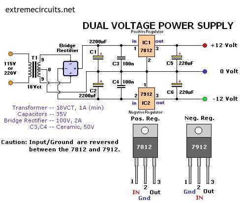
The following circuit diagram of a dual voltage power supply can be used for miscellaneous applications. It requires a few components to build. The most important components of this circuit are regulators: 1: (AN) 7812 and 2: (AN) 7912....
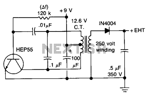
This circuit will generate approximately 300 volts DC at a very low current, sufficient for a GM tube. Caution is advised with the output. The described circuit is a high-voltage DC power supply designed to provide approximately 300 volts, which...
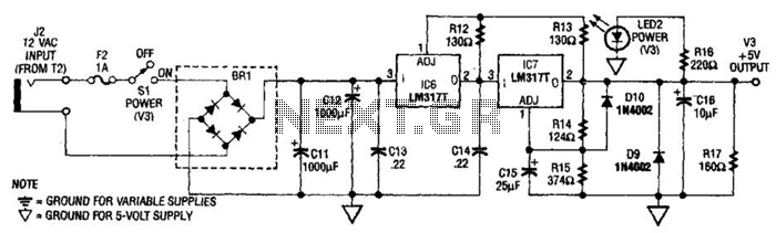
The power supply presented is intended to function with a wall transformer. This circuit can be utilized alongside a variable supply for testing circuits in a laboratory setting. T2 serves as a 12-V wall transformer. The power supply circuit is...