
Simple sound trigger for cameras and flashes

The sound trigger circuit is designed to activate a camera or flash unit in response to sound, making it particularly useful for capturing high-speed events such as balloon pops or other quick occurrences. The fundamental components of this circuit typically include a microphone, an amplifier, a comparator, and a relay or transistor to control the camera or flash.
The microphone serves as the initial sensor, detecting sound waves and converting them into an electrical signal. This signal is then amplified by an operational amplifier (op-amp) to ensure it is strong enough for further processing. The amplified signal is fed into a comparator, which is set to trigger when the sound level exceeds a predefined threshold. This threshold can be adjusted to suit various environments and sound levels.
Upon activation, the comparator output switches from low to high, which can be used to drive a transistor or relay. This component acts as a switch that closes the circuit to the camera or flash, initiating the capture of an image. The relay is particularly useful for isolating the camera's circuitry from the sound trigger circuit, protecting sensitive components from potential damage.
Additional features may include adjustable sensitivity controls, delay timers, or LED indicators to provide visual feedback when the trigger is activated. Power supply options for the circuit can vary, with battery-operated designs being common for portability, while wall adapters may be used for stationary setups.
This sound trigger circuit not only enhances the photography experience but also opens up opportunities for creative experimentation in capturing fleeting moments that would otherwise be difficult to document.This acticle describes how to build a simple yet effective sound trigger for cameras or flashes. The circuit allows to experiment with high-speed photography.. 🔗 External reference
Related Circuits
This figure illustrates the schematic diagram of a simple inductance meter. U1 is a 74LS00 two-input quad NAND gate logic integrated circuit. Two resistors, a capacitor, and a surplus microprocessor crystal create a stable crystal oscillator operating close to...
Here's a simple lie detector that can be built in a few minutes, but can be incredibly useful when you want to know if someone is really telling you the truth. It is not as sophisticated as the ones...
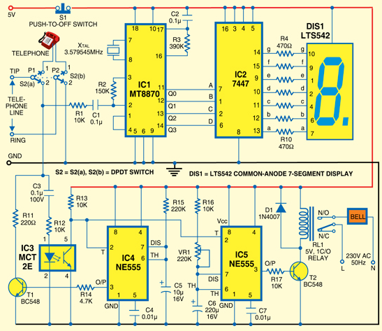
A simple calling bell circuit designed for small offices to summon the office boy using an existing intercom system. The office boy can be called from up to nine locations equipped with extension lines. The system connects to a...
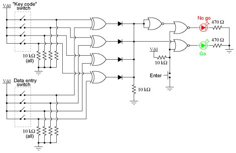
This experiment can be constructed using a single 8-position DIP switch, although utilizing two switch assemblies may facilitate a better understanding of the concept. One switch assembly is designated to hold the correct code for unlocking the lock, while...
555 Timer Sound Effects Videos 1. This project involves creating a light theremin using a 555 timer. It is suitable for spooky Halloween effects. 3. A film countdown timer is included. 4. A UHD chessboard timer is also featured....
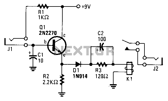
The transistor Q1 remains off until the magnetic switch connected to J1 closes. When this occurs, 9V is supplied through R1 to the base of Q1. As a result, Q1 turns on, which charges capacitor C2 through relay K1,...