
SIMPLE INDUCTANCE METER

The simple inductance meter circuit operates using a crystal oscillator configuration based on the 74LS00 NAND gate IC. The oscillator's frequency is determined by the values of the resistors and capacitor connected to the NAND gates. The circuit's design allows for precise frequency generation, which is crucial for accurately measuring inductance.
In this configuration, the two resistors (R1 and R2) are arranged in a voltage divider setup, which helps establish the biasing conditions for the NAND gates. The capacitor (C1) is responsible for setting the timing characteristics of the oscillator, while the surplus microprocessor crystal (X1) defines the frequency of oscillation. The combination of these components ensures that the circuit generates a stable RF signal.
The RF voltage is taken from pin 8 of the NAND gate, which outputs the oscillating signal. This signal passes through isolation capacitor C3 to prevent any DC offset from affecting the measurement. The output can then be connected to a measuring device, such as an oscilloscope or frequency counter, to determine the inductance of the component under test. The inductance can be inferred from the frequency deviation caused by the inductive load, allowing for precise measurement in various applications.
Overall, this schematic provides a clear representation of the components and their interconnections, making it suitable for those looking to build or understand a simple inductance meter circuit.This figure shows the schematic diagram of the simple inductance meter. U1, a 74LS00 two-input quad NAND gate logic integrated circuit, two resistors, a capacitor, and a surplus microprocessor crystal form a stable crystal oscillator near the marked frequency of the crystal. The RF voltage is taken from pin 8 through isolation capacitor C3 to the measuring.. 🔗 External reference
Related Circuits
This is a VU meter circuit featuring 10 LEDs. This simple LED VU meter consists of only a few components, yet it serves as an effective indicator for sound levels. The circuit is constructed around an unspecified component. The VU...
Electronic potentiometer using a standard CMOS logic and analog multiplexers. Pot have low distortion (0.005% less at 1 V rms) and is it easy for beginners to understand. In the beginning, the art of Hi-Fi, in the absence of...
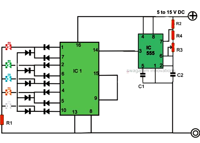
An LED light chaser circuit is an electronic configuration designed to illuminate a group of LEDs in a predetermined sequence. A commonly used integrated circuit (IC) for creating this type of LED sequencer circuit is the 4017. This IC...
In the circuit below, a quad voltage comparator (LM339) is used as a simple bar graph meter to indicate the charge condition of a 12 volt, lead acid battery. A 5 volt reference voltage is connected to each of...
The series of decibel meters functions to determine the signal strength level delivered to the speakers in an audio system. This decibel meter circuit is commonly referred to as VU meters in high-fidelity audio systems. The series of decibel...
This circuit was designed as a small portable DJ mixer for a friend. It is a simple audio mixer circuit featuring two dual logarithmic potentiometers to adjust input signal levels, along with several resistors for mixing. The circuit operates...