
Simple Spectrum Analyzer Adaptor For Scopes Circuit

The circuit operates by leveraging the NE602 chip, which functions as both a mixer and an oscillator. The chip receives an RF signal from the amateur band and mixes it with a local oscillator signal to produce the 455-kHz IF signal. This intermediate frequency is crucial for further processing, as it is easier to amplify and analyze compared to the original RF signal. The amplifier U2 enhances the strength of the IF signal, ensuring that it is adequate for detection.
Detector D2 plays a pivotal role in demodulating the IF signal, converting it into an audio or baseband signal that can be visualized on the oscilloscope. The Y-axis of the oscilloscope displays the amplitude of the detected signal, allowing for real-time monitoring of the frequency spectrum. The horizontal axis, driven by VT, enables the user to sweep across the frequency range, providing a comprehensive view of the signals present within the selected amateur band.
Coils L2 and L3 are critical components in this circuit, as they are specifically designed to resonate at the desired frequencies within the 10 to 15 MHz range. The choice of using toroidal cores from Amidon Associates ensures minimal electromagnetic interference and optimal performance. The variable inductor LI allows for fine-tuning of the circuit, enabling adjustments to be made for different operating conditions or specific frequencies of interest.
Overall, this circuit serves as an effective tool for amateur radio enthusiasts and spectrum monitoring applications, providing a straightforward means to visualize and analyze signals within a designated frequency range. Suitable for monitoring an amateur band or a segment of the radio spectrum, this simple adaptor uses an NE602 mixer-oscillator chip to produce a 455-kHz IF signal, which U2 amplifies, then feeds to detector D2 and the Y axis of an oscilloscope. VT is used to drive the horizontal axis input of a scope. L2 and L3 are coils suitable for the frequency range in use. For this circuit, coils are shown for the 10- to 15-MHz range. L2 and L3 are wound on Amidon Associates, T-37 or T-50 toroidal cores, and LI is a commercial or homemade variable inductor, etc.
Related Circuits
A 30W Class AB power amplifier circuit diagram utilizes a power transistor. To set up the amplifier, adjust the variable resistor R1 to its maximum value and R12 to zero. After completing this setup, activate the amplifier. Adjust R1...
Most cases of infrared remote control failure can be identified by the absence of the pulsed transmitted infrared light. It is very rare that the... Infrared remote controls operate by transmitting modulated infrared light signals that are detected by a...
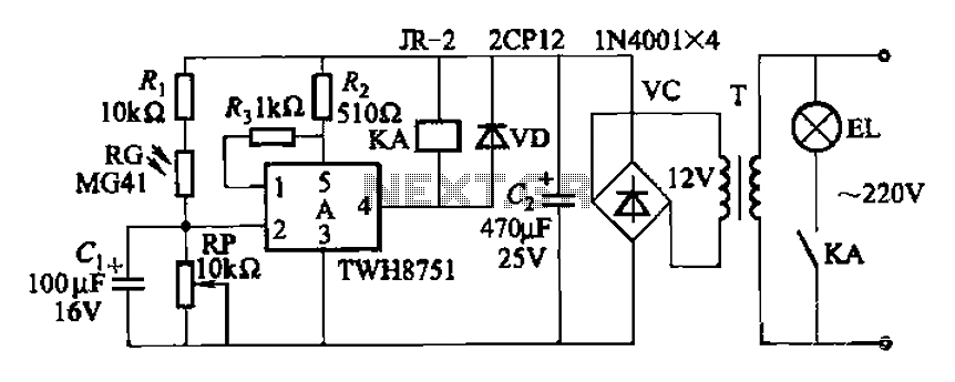
The adjustment potentiometer RP can modify the sensitivity of the device. Capacitors C1 function as an anti-light interference mechanism for instantaneous action. The adjustment potentiometer (RP) is a variable resistor that allows for fine-tuning of the device's sensitivity. By altering...
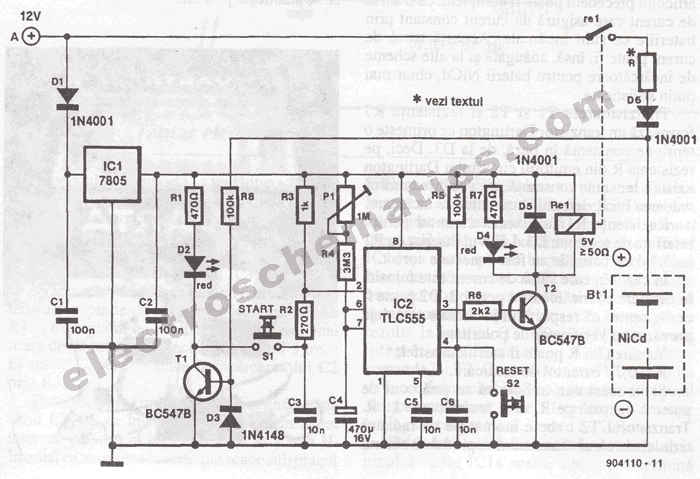
The portable battery charger has been designed to enable the charging of NiCd batteries outdoors using a 12 V vehicle battery. The portable battery charger is engineered to facilitate the charging of Nickel-Cadmium (NiCd) batteries in outdoor environments, leveraging the...
The time is set by potentiometer R2, which provides a range from 1 second to 100 seconds, using a timing capacitor C1 of 100 µF. The output at pin 3 is normally low, keeping the relay in the off...
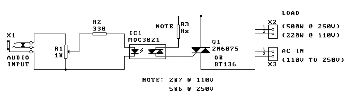
A music-to-light modulator is a circuit which controls the intensity of one or more lights in response to an audio input. The problem in older circuits is that there was a direct electrical connection between the lights using mains...