
Simple step down dc converter multi voltage

The described circuit operates as a DC voltage regulator, specifically designed to convert a higher DC input voltage to lower, stable output voltages suitable for various applications. The circuit employs a linear voltage regulator or a switching regulator topology, depending on the design requirements.
In a typical linear regulator configuration, the circuit utilizes a series pass element, often a transistor, to control the output voltage. The fixed resistor R1 plays a crucial role in setting the reference voltage and stabilizing the output. The circuit may also include additional components such as capacitors for input and output filtering, which help to smooth out voltage fluctuations and reduce noise.
For a switching regulator implementation, the circuit would employ an inductor, diode, and a switching element (like a MOSFET) to efficiently convert the input voltage to a desired lower output voltage. This method is beneficial for applications requiring higher efficiency, especially when dealing with larger differences between input and output voltages.
The output voltage can be adjusted by selecting appropriate values for R1 and other components, allowing the circuit to cater to various voltage requirements. Additionally, feedback mechanisms are often integrated to maintain output voltage stability under varying load conditions.
Overall, this circuit serves as a versatile solution for providing multiple regulated DC output voltages, making it suitable for powering various electronic devices and systems.This again the one circuit that can is dc regulator the many voltage get simplely. Or Simple step down dc converter multi voltage. By have R1 be formed fix the.. 🔗 External reference
Related Circuits
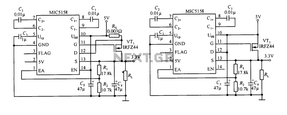
The circuit consists of peripheral components for the MIC5158, a linear regulator that converts a 5V input into a 3.3V output with a maximum current of 10A. When the input voltage (Ui) is 5V, an N-channel MOSFET, specifically the...
A DC/DC step-up converter is suitable for use in battery-powered equipment. This converter can be employed to generate supply voltages for internal circuits. The DC/DC step-up converter, also known as a boost converter, is a critical component in various electronic...
Manual stabilizers remain popular due to their straightforward construction, affordability, and high reliability, as they do not incorporate any relays. Manual stabilizers are widely utilized in various electronic applications, primarily due to their effective voltage regulation capabilities. These devices function...
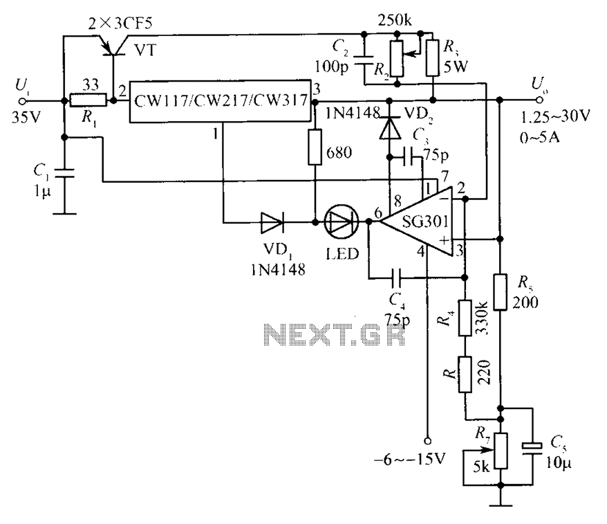
This document presents a diagram of a constant voltage/current power supply box. It is composed of three main components: spread current, constant voltage, and constant current. The design features two 3CF5 power transistors arranged in parallel, functioning as an...
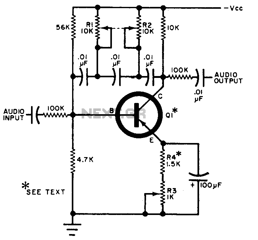
The circuit can be selectively tuned to two closely related tones. The selective frequency is determined by the values of the feedback circuit connected to the collector and base of Q1, which includes capacitors and resistors. When the specified...
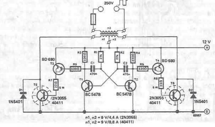
A simple portable converter that transforms 12V to 250V can be constructed using this circuit diagram. This converter is intended for portable use with a 12V car battery. A built astable multivibrator, consisting of transistors T1 and T2, generates...