
Under-Over-Voltage Beep for Manual Stabiliser

Manual stabilizers are widely utilized in various electronic applications, primarily due to their effective voltage regulation capabilities. These devices function by adjusting the output voltage to maintain a consistent level despite fluctuations in the input voltage. The simplicity of their design often includes a transformer, rectifier, and filter circuit, which work together to stabilize the output.
The absence of relays in manual stabilizers contributes significantly to their reliability and longevity. Without mechanical components, the risk of failure from wear and tear is minimized, making them suitable for environments where durability is essential.
In terms of construction, a typical manual stabilizer may consist of a step-down transformer that reduces the high voltage AC input to a lower level. The output from the transformer is then rectified using diodes, converting AC to DC. Following this, a filter capacitor smooths out the rectified voltage, providing a steady DC output.
Additionally, manual stabilizers often feature adjustable output settings, allowing users to select the desired voltage level. This adjustability is achieved through a potentiometer or variable resistor, enabling fine-tuning of the output voltage to meet specific requirements.
Overall, the combination of simple circuitry, cost-effectiveness, and robust performance makes manual stabilizers a preferred choice for many applications, including powering sensitive electronic devices and ensuring stable operation in varying electrical conditions.Manual stabilisers are still popular because of their simple construction, low cost, and high reliability due to the absence of any relays while covering.. 🔗 External reference
Related Circuits
This beeper circuit utilizes two 555 integrated circuits (ICs) and can operate within a supply voltage range of 5 to 15V DC. It is suitable for applications requiring an alarm or beeping signal. The first IC (IC1) is configured...
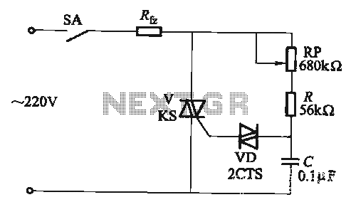
The adjustment potentiometer RP allows for the modification of the TRIAC conduction angle, facilitating temperature control applications. The adjustment potentiometer (RP) serves a crucial role in controlling the conduction angle of the TRIAC, which in turn regulates the power delivered...
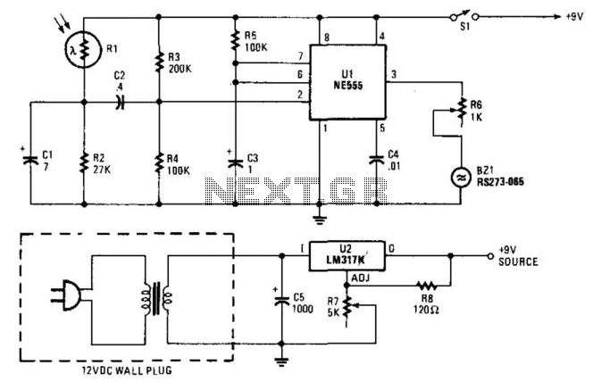
When the light on the answering machine blinks, the resistance of photoresistor Rl increases, triggering the timer (U1) and generating a 0.2-second pulse that activates BZ1. Rl is optically coupled to the LED on the answering machine and is...

Repair the circuit in the switchboard that supplies power to appliances such as water heaters and electric irons to provide a reminder that the load is on. An LED will blink to indicate the load status, and a buzzer...
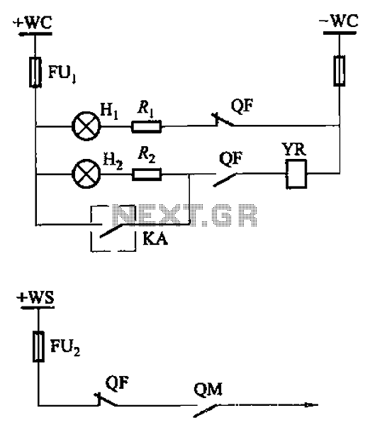
The CS2 type is a manually operated breaker mechanism commonly utilized for AC power operation and manual control signal circuits, as depicted in Figure 6-68. The circuit includes various components: wc for small signal bus control, QF for auxiliary...
In various electronics-level adjustments, such as LED drivers for LCD panel backlight controls, the AD5228 can be utilized. A manually adjustable LED driver is illustrated. The AD5228 is a dual-channel, digitally controlled potentiometer (DCP) that can be employed in applications...