
Simple Surround Sound Decoder

The described surround-sound decoder utilizes the Hafler principle, which effectively creates a pseudo-surround sound experience by deriving a rear channel signal from the difference between the left and right audio channels. In a typical stereo setup, the decoder processes the incoming stereo signals to generate an output that can drive additional speakers placed behind the listener, thereby enhancing the spatial audio experience.
The circuit typically involves a differential amplifier configuration that takes the left and right channel inputs and computes their difference. This difference signal is then amplified to drive the rear speakers. The output stage of the decoder must be carefully designed to ensure that it can handle the varying power demands of the rear speakers, particularly in setups where the main speakers are bi-amped or bridged.
In cases where the main speakers are bi-amped, the absence of a full-range signal can lead to inadequate power for the rear speakers, as the decoder relies on the difference signal, which may not be sufficient in such configurations. Additionally, the decoder lacks a level control mechanism, resulting in a fixed output level that may not match the desired volume for the rear speakers.
To address these limitations, an adjustable gain stage could be integrated into the circuit to allow for fine-tuning of the rear speaker output. This could be achieved with a variable resistor or potentiometer that adjusts the gain of the difference signal before it reaches the rear speaker outputs. Furthermore, to ensure compatibility with mono signals, a summing amplifier could be included to combine the left and right channel signals, producing a suitable output for the rear speakers even when the input is not stereo.
In summary, while the Hafler surround-sound decoder provides a straightforward solution for creating a surround sound experience, careful consideration must be given to its design, particularly in systems with bi-amped or bridged main speakers, to ensure optimal performance and control over the rear channel output.This surround-sound decoder is based on the "Hafler" principle, first discovered by David Hafler sometime in the early 1970s. The original idea was to connect a pair of speakers as shown in Figure 1, for use as the rear speakers in the surround setup.
This is ok just as it stands, but problems are created if the main speakers are bi-amped or using bridging, for example, since there is no longer a full-range / full power signal available for the rear speakers. There is also no way to control the level reproduced, since it will always simply be the difference signal between left and right channels.
If the signal is mono, then the signal in both channels will always be more or less identical, and there will be no output from the rear speakers at all. 🔗 External reference
Related Circuits

A simple lab power supply electronic project can be designed using this circuit diagram, which is based on the LM2576 monolithic integrated regulator that provides all the active functions for a step-down (buck) switching regulator. As seen in the...
This circuit generates a two-tone effect similar to the cuckoo song. It can be used for doorbells or other applications due to a built-in audio amplifier and loudspeaker. As a sound effect generator, it can be connected to external...

This DC negative-voltage generator based on the 555 produces a negative output voltage equal to approximately 2 times the DC supply voltage. The described circuit utilizes the popular 555 timer IC configured in an astable or monostable mode to generate...
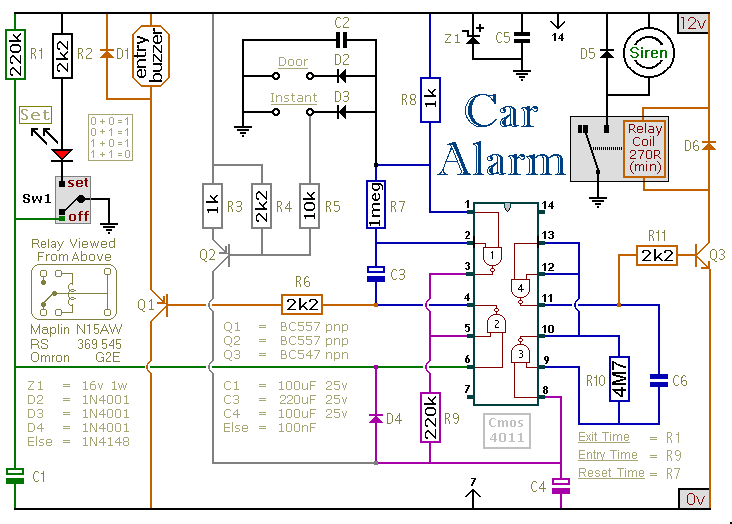
This circuit includes automatic exit and entry delays, an optional instant alarm zone, an optional intermittent siren output, and an automatic reset feature. By incorporating external relays, it is possible to immobilize the vehicle and activate the lights. For...
The circuit under discussion is a four-siren sound generator utilizing the UM3561 integrated circuit (IC), which is a low-power CMOS device. Four distinct sounds can be generated by activating switches S1, S2, and S3. This circuit is versatile and...
This circuit diagram represents a simple yet effective transmitter circuit, capable of transmitting telephone conversations. When the telephone receiver is on the hook, the line voltage is approximately 48 volts. The R7 preset resistor is adjusted to achieve a...