
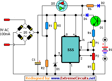
Simple Negative Supply Circuit

The described circuit utilizes the popular 555 timer IC configured in an astable or monostable mode to generate a negative output voltage. The principle behind this design involves the use of charge and discharge cycles of a capacitor, which are controlled by the timing resistors and capacitor connected to the 555 timer.
In this configuration, the 555 timer is powered by a positive DC voltage supply. When the timer operates, it alternately charges and discharges the capacitor, which creates a square wave output. By employing a specific transformer or inductor in conjunction with a rectifier circuit, the output can be inverted to produce a negative voltage.
The output voltage can be regulated to reach approximately twice the magnitude of the input supply voltage, depending on the design of the transformer and the load connected to the circuit. This is particularly useful in applications requiring a negative voltage rail for operational amplifiers, sensors, or other electronic components that require a dual power supply setup.
To ensure stability and efficiency, it is essential to select appropriate values for the timing components (resistors and capacitors) and to consider the load conditions. Additional filtering capacitors may also be included at the output to smooth out any ripple voltage, thereby improving the overall performance of the negative-voltage generator.
Overall, this 555-based negative-voltage generator offers a simple and effective solution for generating a negative voltage supply in various electronic applications. This dc negative-voltage generator based on the 555 produces a negative output voltage equal to approximately 2x the dc supply voltage.
Related Circuits
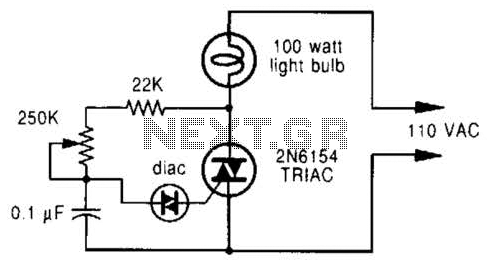
A phase-controlled dimmer delays the triac turn-on to a selected point in each successive AC half cycle. This circuit is suitable only for incandescent lamps, heaters, soldering irons, or universal motors that have brushes. A phase-controlled dimmer is an electronic...
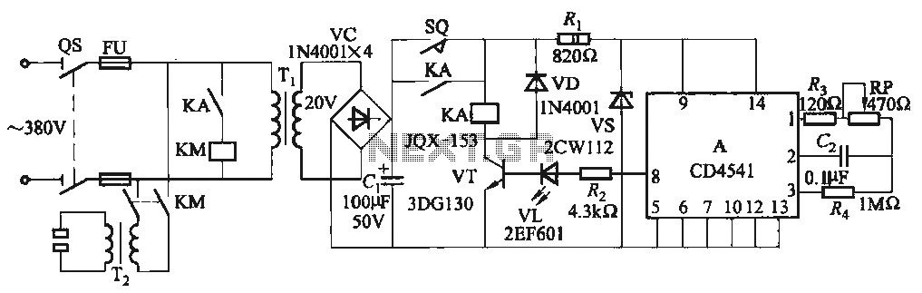
One Foot Spot Welder circuit. The circuit utilizes the IC CD4541 to provide precise delay characteristics, enabling the electrical time constant necessary for effective welding. This ensures consistent welding quality across identical weldments. For varying weldments, the electrical locator...
The MDRC committee approached the author to take on the role of Electronic Components and Project Officer, which was accepted without hesitation. Upon assuming the position, it became evident that more time would be required than initially anticipated, primarily...
The BTS412B functions as two high-side power MOSFET switches, while the BU271L components rated for 50V serve as the low-side switches. Together, these elements can form a bi-directional H-bridge DC motor drive circuit, as depicted in Figure 11-1l. This...
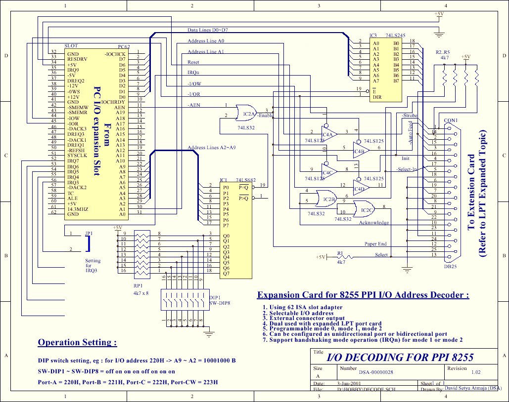
The PPI-8255 is a general-purpose I/O programmable interface that is typically connected directly to a computer bus. This article demonstrates that the card can serve dual purposes: as an expander port and for direct I/O functionality. The card can...
This automatic NiCd charger for 9V NiCd batteries utilizes the properties of a 555 timer and is straightforward to construct. The design allows for continuous charging of the battery without the risk of overcharging or discharging. With the specified...