
Simple Surround Sound Decoder

The described surround-sound decoder circuit utilizes the Hafler principle to enhance audio experiences by effectively managing the difference signals between stereo channels. The implementation of this circuit requires careful consideration of component selection, particularly regarding transformers and op-amps. The passive circuit design, while straightforward, hinges on the availability of a suitable transformer that meets the specified impedance and ratio requirements. The challenges associated with sourcing quality transformers necessitate an exploration of active circuit alternatives.
The active circuit design employing a dual op-amp offers a more reliable solution by ensuring consistent performance across varying impedance levels. This configuration not only enhances bass response but also provides flexibility in integrating with existing audio systems. The careful arrangement of components within the circuit allows for effective signal manipulation without compromising the integrity of the main left and right audio channels. The decision to exclude a volume control simplifies the design while maintaining functionality, as the preamp serves this purpose.
In conclusion, the proposed circuit presents a viable method for implementing surround sound in audio systems, effectively utilizing the Hafler principle while addressing common challenges associated with passive designs. The emphasis on active components ensures compatibility with a wide range of audio equipment, making this a practical choice for enhancing audio playback in surround sound applications.This surround-sound decoder is based on the "Hafler" principle, first discovered by David Hafler sometime in the early 1970s. The original idea was to connect a pair of speakers as shown in Figure 1, for use as the rear speakers in the surround setup.
This is ok just as it stands, but problems are created if the main speakers are bi-amped or using bridging, for example, since there is no longer a full-range / full power signal available for the rear speakers. There is also no way to control the level reproduced, since it will always simply be the difference signal between left and right channels.
This circuit works by allowing the rear speakers to reproduce only the difference signal between the left and right outputs. All stereo encoded material has some difference between left and right channels (if it didn`t, it would be mono), and it is this difference signal that is reproduced by the rear speakers.
It is important to ensure that the connection between the rear speaker negative terminals is not earthed, or they will simply be in parallel with the main speakers. So, if you want to use separate amps for the rear speakers, basically you can`t - unless you get sneaky.
The first circuit in Figure 2 is completely passive, but requires that a suitable transformer is available. A suitable transformer means a line level, 10k impedance unit with a 1:1 ratio - these are very scarce (I would suggest almost impossible to get).
You might be able to get away with a 600 Ohm unit, but because of the impedances you need, its performance will be very ordinary, with an extreme lack of bass (there is not enough inductance for a 600 Ohm transformer to work satisfactorily at high impedances). Loading the transformer will give back some of the bass, but the preamp is unlikely to be very happy with the resulting impedance.
The circuit shown is not a bad compromise, although the impedances are too low for anything other than a solid state preamp (preferably using opamps). Using a telephony transformer (600 Ohm), the loss overall is about 3dB, with a low frequency -3dB point around 100Hz.
This will vary depending on the quality of the transformer used, so experimentation will be needed. Although 600 Ohm telephony transformers are reasonably readily available, many of them are pretty nasty (actually, disgusting is probably closer). My tests were on a really good one, built by an Australian company called Transcap. I think I can say with some certainty they will be rather unwilling to sell one-off quantities. Another manufacturer of really nice transformers is Midcom in the US, but you will have the same problem with them.
These manufacturers are set up to deal with large orders from other companies, not the likes of you and me wanting one ("You want. ONE ") transformer. As a result you will have to take whatever you can get. Since it is unlikely that this will be viable for most constructors, the alternative is to go active, using a dual opamp to perform the functions.
This is described next. The schematic shown in Figure 2 is a simple way to achieve the same thing (with some additional benefits) at line level (i. e. before the signal reaches the power amplifiers - in a bi-amped system, this circuit must be between the preamp and the electronic crossover).
The extras available are readily apparent: Although there have been similar circuits published over the years, this is a little different in a few areas. I wanted to avoid having any active electronics in the main Left and Right channels, since this eliminates any possibility of sound degradation due to the introduction of the opamps.
The input impedance of 50k will not pose a problem for any preamp (including valve types), and the main signal is simply in parallel with the additional circuitry. No volume control has been included, since you already have one in the preamp. It would just become another component to fiddle with, and sinc 🔗 External reference
Related Circuits
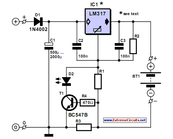
A simple NiCd charger can be constructed using readily available components and an economical LM317 or 78xx voltage regulator. The design incorporates a current limiter made up of resistor R3. The proposed NiCd charger circuit utilizes an LM317 or a...
Currently, there is a growing trend to utilize telephone lines for long-range control and alarm systems within transmission mediums, which is accompanied by extensive research. Such systems typically consist of alarm devices and police notification arrangements, including a central...
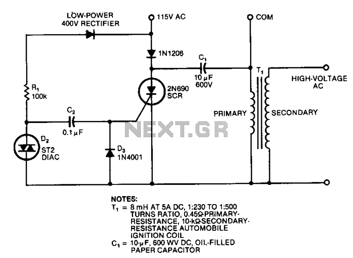
This circuit generates high-voltage pulses using an inexpensive auto ignition coil. By adding a rectifier to the output, the circuit produces high-voltage direct current (DC). The input to the circuit is 115 Vac. During the positive half cycle of...
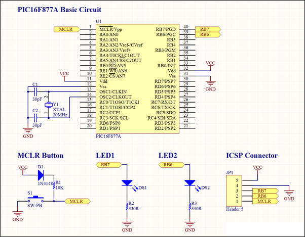
This project involves a basic LED blinking circuit utilizing the PIC16F877A microcontroller. It features two LEDs connected to the PIC16F877A, with the source code adapted from the 16F template. The circuit design consists of the PIC16F877A microcontroller, which serves as...
This low-cost short-wave transmitter is tunable from 10 to 15 MHz using a ½J gang condenser (VC1), which determines the carrier frequency in conjunction with inductor L1. Frequency trimming is achieved with VC2. The carrier signal is amplified by...
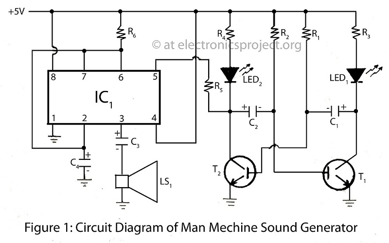
The Man Machine Sound Generator is a unique project within a series of alarm circuit diagrams, featuring descriptions of various types of alarm projects. The Man Machine Sound Generator is an innovative electronic circuit designed to produce sound signals in...