
simple touch switch circuit

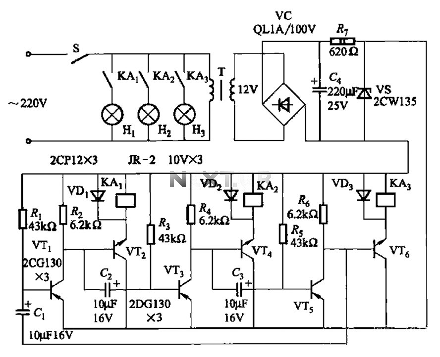
This transistor-based touch switch circuit is an innovative solution for activating electrical loads without the need for traditional mechanical switches, which can be prone to failure in harsh conditions. The core of the circuit consists of a few transistors configured to detect the capacitance change when a user touches the metal plate, which serves as the touch sensor. The activation of the transistor allows current to flow to the relay coil, engaging the relay contacts to power the connected load.
The circuit can be powered by a standard 12V DC supply, making it compatible with various applications. The use of a latching relay is particularly advantageous, as it maintains the state of the load (on or off) even after the user removes their finger from the touch pad. This feature is beneficial for applications where continuous operation is desired without the need for constant user interaction.
To implement the touch pads, PCB material can be utilized for a more durable and reliable touch surface. The pads can be connected to the base of the transistors through a resistor, which helps to limit the current and protect the components from potential damage. The design allows for easy integration into existing systems, making it a versatile solution for various electronic projects.
For the second circuit that interrupts power to the latching relay, a standard relay can be employed. This relay will be activated by the second touch pad, which, when pressed, opens the normally closed contacts connected to the power supply of the latching relay, effectively turning off the load. This arrangement allows for a simple and intuitive user interface, where one touch pad activates the load and the other deactivates it.
Overall, this touch switch design is suitable for applications requiring reliable switching capabilities in environments where traditional switches may fail, offering a robust and user-friendly solution for controlling electrical loads.Similar to the CMOS based Touch Switch also on this site, this transistor based touch switch can activate a load simply by the user touching a metal plate. It is designed to directly switch a relay to allow it to be used with large loads. As it uses only a few commonly available transistors and a 12V supply, it is ideal for hostile environments wh
ere mechanical switches would be damaged. Using a latching relay and two of these circuits, a simple two pad "touch on/touch off" arrangement can be made. The touch pad can be most easily made by cutting a small square of PCB material and then soldering on a single wire.
Alternatively, something like a penny glued to a plastic backing will do the job. As mentioned, a latching relay can be used so that a momentary touch activates the relay and it remains active. To turn off a latching relay, power must be interrupted. So a 2nd circuit with a normal relay can be used to cut power (use the NC contacts on the 2nd circuit).
Placed side by side, two touch pads form an "on" and an "off" pad. 🔗 External reference
Related Circuits
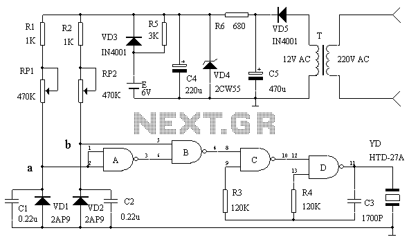
This circuit serves as an over-temperature alarm and cooling system utilizing CD4011 four NAND gate integrated circuits to monitor the oven's temperature. In the event of a thermostat circuit failure or power outage, if the internal temperature exceeds or...
The transistors VTi, VT3, and VTs, along with the RC components, form three distinct multi-resonator oscillators. The oscillation frequency levels are dependent on the values of Ri, R3, Rs, and Cl, as well as Cz and C3s. The circuit comprises...
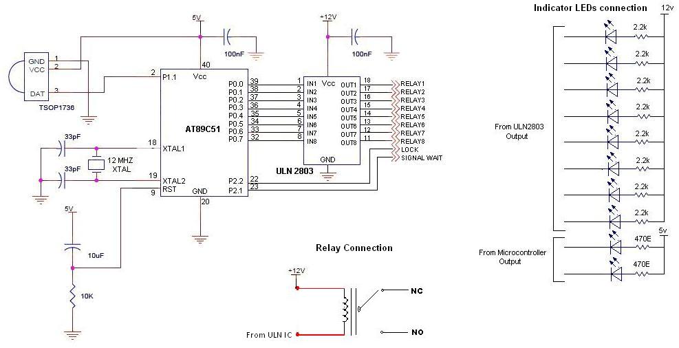
To control multiple switches, it is necessary to transmit several bits via infrared (IR) transmission to indicate which key is pressed on the remote control and, consequently, which switch on the switchboard to operate. This project utilizes a commercially...
The initial intention was to name the product "Chimera," but due to an existing synth company with that name, it was decided to use "Cerberus" to avoid confusion. The term "Tricephalic Filter" was deemed less appealing. Similar to its...
This circuit was used to stop all the BFO drift. The circuit is extremely stable. Turn the receiver off, and then on at any time and temperature, the BFO frequency is exactly the same. The resonator is a Murata...
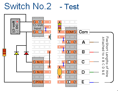
The prototype of Keypad Switch No. 2 was constructed using only the stripboard layout as a reference. If the layout has been accurately reproduced, a functional circuit will result. Once the layout is confirmed to be correct and a...