
Simple TV Transmitter circuit diagram (VHF)
")
The circuit diagram described facilitates the transmission of television signals over moderate distances, making it suitable for various applications, such as local broadcasting or experimental setups. The choice of the BC 108 transistor is critical for achieving optimal performance, as it can handle the required frequency range and provide adequate amplification.
When constructing the inductor L1, the specifications regarding the number of turns and wire gauge are crucial for tuning the circuit to the desired frequency. The use of #24 enameled wire is recommended for its balance between resistance and inductance, which influences the overall efficiency of the transmitter. The air core inductor design allows for a lightweight and compact solution, essential for portable or DIY applications.
For those unable to source the specified transistor, alternatives like the BC337, 2N2222, or BC546 are suitable substitutes, each offering similar electrical characteristics. This flexibility ensures that builders can complete their projects without being hindered by component availability.
In summary, this circuit diagram serves as a practical guide for individuals interested in TV transmission technology, providing essential details on component selection and construction techniques to achieve successful signal transmission.Most of people ask TV transmitters. So Today I`m going to give you a very useful circuit diagram. By using this circuit you can send your signals 75m to 100m. This circuit diagram is not my own circuit one of my friends gave me this. I suppose you guys also can send your own circuit diagrams for us. Then we can publish them through our website. Here The y have used common transistor BC 108 If you are unable to find this transistor you can use equal transistors like Bc337 2n2222 Bc 546 # To make L1 wound 6 turns of #24 enameled wire on a 10mm air former for frequency 60 - 80 MHz For 150 - 180 MHz wound 4 turns and for 180 - 200MHz wound 2 turns. 🔗 External reference
Related Circuits
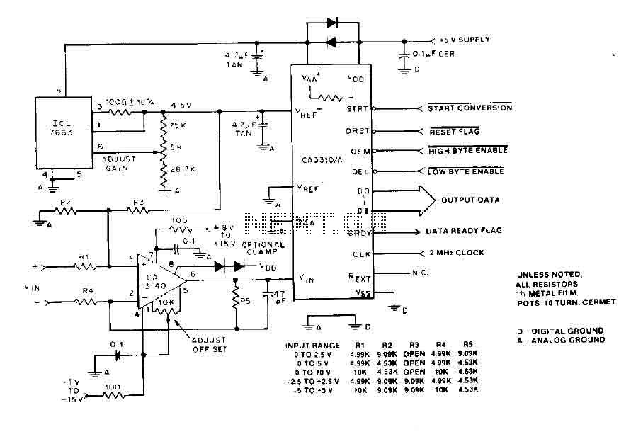
The BiMOS CA3140 operational amplifier offers excellent orientation capabilities for high bandwidth signal inputs and can swiftly adjust the energy output at its terminal CA33IO WINE. The CA3140 can also operate close to the negative supply rail. If the...
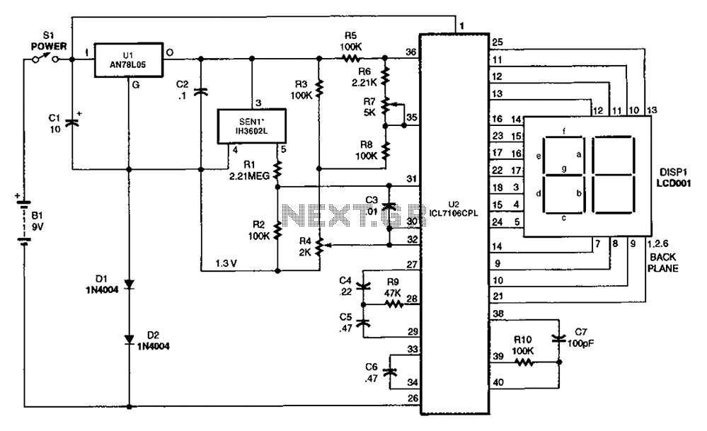
The output DC voltage of sensor SEN1 changes linearly in response to variations in relative humidity. This DC voltage is routed through resistors R1 and R2 to the analog-to-digital (A/D) converter chip U2. Resistor R4 is connected to ground,...
The single-813 crystal oscillator transmitter, designed by RCA, was showcased in an advertisement on the back page of a 1938 "QST" magazine and published in the RCA HamTips bulletin, volume 1, number 4, dated December 1938. This transmitter delivers...
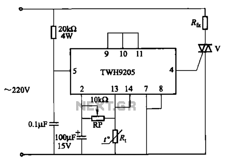
This circuit is used for temperature control in various heating equipment such as water heaters, microwave ovens, air conditioners, refrigerators, fans, and automatic fire extinguishing devices. It includes a negative temperature coefficient (NTC) thermistor as the temperature sensing element...
A DIY GSM jammer schematic diagram designed specifically for GSM1900 frequencies ranging from 1930 MHz to 1990 MHz. The GSM1900 mobile phone network is utilized in the USA, Canada, and most South American countries. This cell phone jammer is...
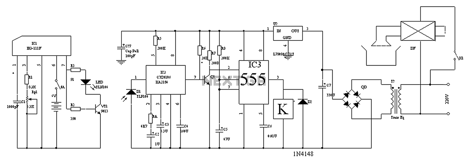
The circuit diagram for the automatic control of drinking fountains is presented below. The automatic control circuit for drinking fountains typically employs a combination of sensors and control elements to manage the operation of the fountain efficiently. The main components...