
Simple VCO with 1 transistor

Unijunction transistors (UJTs) are a type of three-terminal semiconductor device that exhibit unique characteristics suitable for oscillation applications. They are particularly valued for their simplicity and effectiveness in generating sawtooth waveforms, which can be utilized in various electronic circuits, including timers, pulse generators, and relaxation oscillators.
A typical UJT circuit configuration includes a UJT connected in a basic oscillator setup with a resistor-capacitor (RC) network. The circuit may consist of a power supply, a resistor (R1) connected to the base of the UJT, and a capacitor (C) connected to the emitter terminal. The capacitor charges through the resistor, and when the voltage across the capacitor reaches the peak point of the UJT's intrinsic standoff ratio, the UJT conducts, discharging the capacitor rapidly and generating a sawtooth waveform.
The frequency of the oscillation can be controlled by adjusting the values of the resistor and capacitor in the RC network. Specifically, increasing the resistance or capacitance results in a lower frequency output, while decreasing these values leads to a higher frequency output. The relationship between the voltage applied to the UJT and the frequency of oscillation is inverse; as the voltage increases, the frequency decreases, making UJTs effective for voltage-to-frequency conversion applications.
In practical applications, UJTs are often used in conjunction with additional components such as diodes and transistors to enhance performance or to create more complex waveforms. The versatility and ease of use of UJTs make them a popular choice for hobbyists and engineers alike in various electronic projects.Unijunction transistors are very intresting. They love to be used in oscillators, and it doesn't takes too many part or very much coaxing to get their sawtooth outputs. This litle squealer will tell you how much voltage it'a connected to. The higher the voltage, the lower frequency output you'll hear. 🔗 External reference
Related Circuits
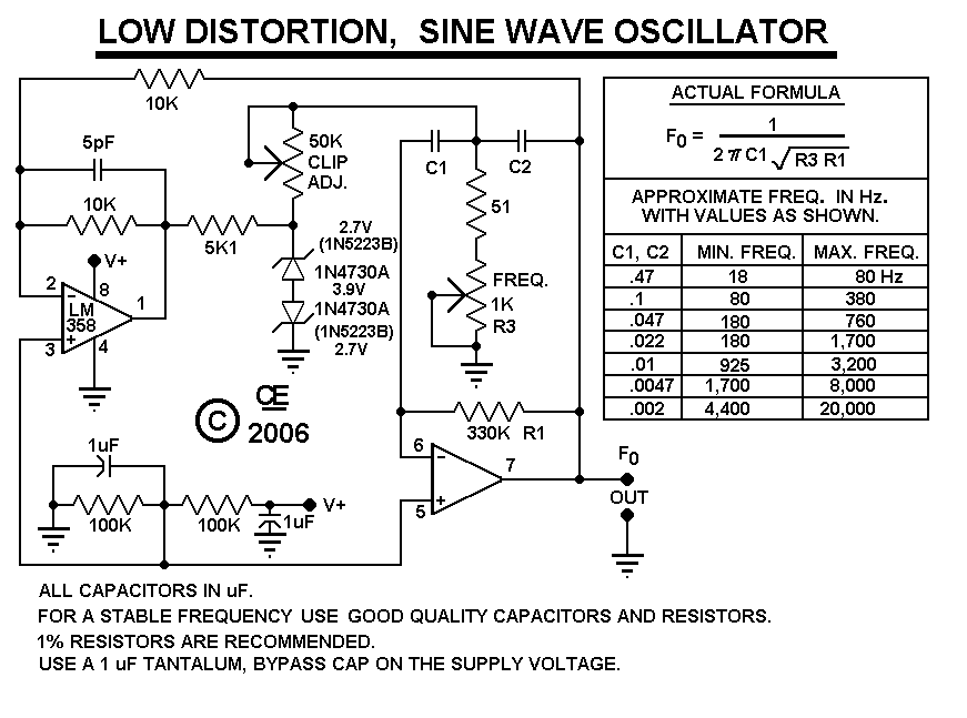
After constructing the device, adjust the frequency to the desired level using the "Frequency Control." Then, utilize an oscilloscope to fine-tune the waveform for optimal performance with the "Clip Control." The sharp rise and fall times of square waves...
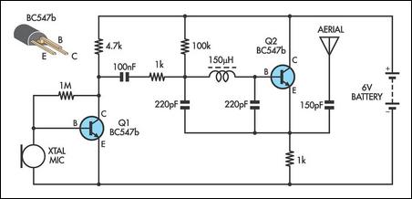
This AM transmitter is notably simple to construct due to its design, which features a non-tapped inductor with a single winding. The inductor is not custom-wound, as it can be sourced from readily available RF chokes, such as the...
This simple circuit generates a good and stable 1V peak-to-peak square wave at 100Hz, 1KHz and 10KHz using a single 1.5V cell as power supply. An useful feature of this circuit is that frequency changes can be obtained by...
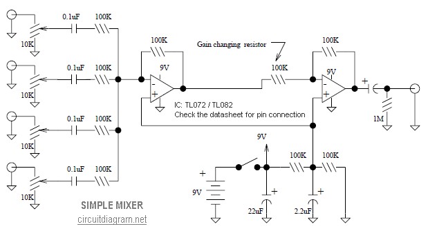
This is a simple mixer featuring four inputs and two operational amplifiers (op-amps). It is designed for mixing microphones or effects outputs. The overall gain from input to output is unity when the potentiometer associated with the input is...
Both converters utilize CMOS inverters. Figure 105-1A illustrates a free-running circuit where both pulse duration and pulse pause are influenced by the temperature of diode D8. This configuration is suitable for applications where synchronization between the converter and other...
This circuit disrupts the infrared receiver in a television by generating a continuous signal that interferes with the remote control signals, preventing the TV from recognizing channel changes or other commands. This allows for uninterrupted viewing of a chosen...