
Simple Square wave Generator

The described circuit utilizes a single 1.5V power supply to generate a square wave output, which can be adjusted to three distinct frequencies: 100Hz, 1KHz, and 10KHz. The circuit operates efficiently, drawing a current of approximately 600µA.
The core component of this circuit is likely a 555 timer IC configured in astable mode, which is a common approach for generating square waves. The frequency of oscillation in such a configuration is determined by two resistors and a capacitor. In this case, the design allows for easy frequency adjustments by swapping out just one capacitor, which simplifies the process of tuning the circuit for different applications.
The square wave output is specified to have a peak-to-peak voltage of 1V, which indicates that the circuit is designed to operate within low voltage levels, making it suitable for battery-powered applications. The stability of the output waveform is crucial for various applications, including clock signals in digital circuits, timing applications, and audio signal generation.
The choice of using a single capacitor for frequency adjustment is an efficient design feature, as it minimizes the number of components that need to be changed for different frequency outputs. This modular approach allows for quick reconfiguration of the circuit without extensive modifications.
Overall, this circuit exemplifies a straightforward and effective method for generating low-frequency square wave signals with minimal power consumption, making it suitable for educational purposes, prototyping, and low-power applications.This simple circuit generates a good and stable 1V peak-to-peak square wave at 100Hz, 1KHz and 10KHz using a single 1.5V cell as power supply. An useful feature of this circuit is that frequency changes can be obtained by switching only one capacitor at a time.
Current consumption is about 600µA. 🔗 External reference
Related Circuits

Programming of the PIC microcontroller is required prior to its utilization in this circuit, which necessitates the use of a programmer. A suitable programmer can be located by searching for "Multi-PIC Programmer." The PIC microcontroller serves as the core component...
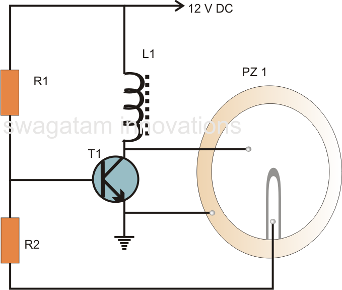
A very simple piezoelectric buzzer can be constructed with minimal electronic components, requiring just a single transistor, a coil, and a piezo buzzer to produce a sound that may be quite piercing. This buzzer circuit operates in a unique...
To put the relay in tension the 4 buttons S1 S4 must be pressed. If anyone of the 4 buttons S5 S8 are pushed the relay doesn't tension (doesn't receive supply voltage). The supply voltage must be equal to...

The pulse generator consists of two low-power CMOS chips that produce a precise pulse width ranging from 50 to 500 ns. IC1 is a dual monostable multivibrator (one shot) where each positive trigger pulse initiates simultaneous positive output pulses...
An ultrasonic sound wave can be generated using an electronic circuit. This simple electronic circuit can generate an ultrasonic wave with a frequency range of 12 kHz and above. The electronic circuit designed for generating ultrasonic sound waves typically utilizes...
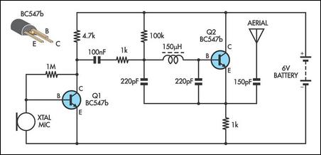
This AM transmitter is notably simple to construct due to its design, which features a non-tapped inductor with a single winding. The inductor is not custom-wound, as it can be sourced from readily available RF chokes, such as the...