
Simple voltage doubler

The LTC1044 is a versatile switched-capacitor voltage converter that operates by transferring charge between capacitors to achieve voltage multiplication. In this application, it effectively doubles the input voltage, which is particularly useful when powering devices that require higher voltage levels than what is provided by standard battery cells.
The circuit configuration typically includes two main capacitors, a switching control circuit, and the necessary passive components for optimal operation. The capacitors are charged and discharged in a controlled manner, allowing the circuit to generate a stable output voltage. When powered by two 1.5 V cells, the LTC1044 can produce an output voltage of approximately 6 V, which is suitable for most low-power CMOS devices.
Key considerations in the design include ensuring that the load current does not exceed the specified limit of 1.75 mA to maintain high efficiency. The efficiency of over 90% is particularly noteworthy, as it allows for prolonged operation of the connected devices without the need for frequent battery replacement or recharging.
The output voltage versus loading characteristics, as indicated in the referenced figure, provide essential insights into how the circuit performs under varying load conditions. This performance data is critical for engineers when selecting components and designing systems that rely on this voltage conversion technique. Overall, the LTC1044 circuit is an effective solution for applications requiring a higher voltage supply from compact battery sources.This circuit doubles available battery voltage using an LTC1044 switched-capacitor voltage converter. The circuit will drive low-power 74-CMOS (3-to 15-V) equipment for extended periods of time from two small 1.
5-V cells. Efficiency exceeds 90% for load currents below 1. 75 mA. Figure 8-7B shows output voltage versus loading (shown as VOUT=6 V). 🔗 External reference
Related Circuits
This is a simple high-voltage inverter circuit. It uses an NPN transistor type 2N3055. This circuit is designed to invert low voltage to high voltage. The high-voltage inverter circuit utilizing the 2N3055 NPN transistor serves as an effective means to...
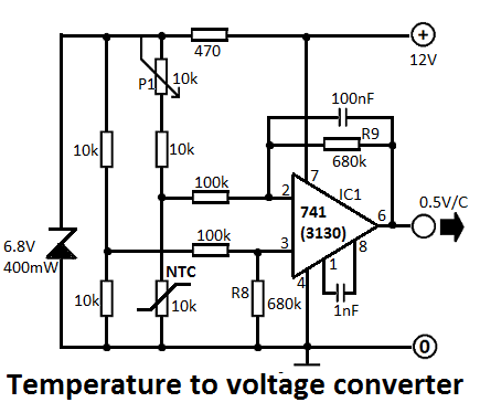
This simple temperature-to-voltage converter circuit allows for precise measurement of room temperature using an NTC resistor or thermistor. The temperature-to-voltage converter circuit typically employs a negative temperature coefficient (NTC) thermistor, which exhibits a decrease in resistance as temperature increases. This...
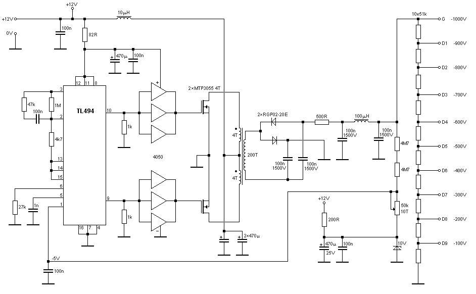
The schematic diagram originates from a circuit designed for a stable power supply ranging from -100V to -1000V. For further details, refer to the page that explains the circuit diagram associated with this power supply. This stable power supply...
This circuit utilizes the widely available LM3914 integrated circuit (IC). The IC is straightforward to operate, does not require external voltage regulators due to its built-in voltage regulation feature, and can be powered from nearly any voltage source. The LM3914...
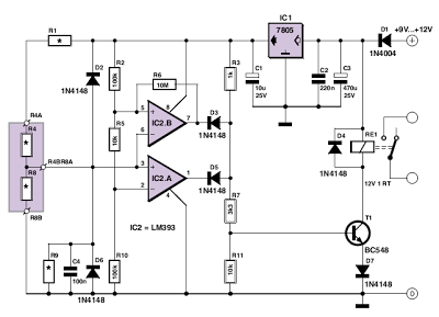
This circuit utilizes two comparators configured as a window comparator. Resistors R2, R5, and R10 establish a voltage window within which the voltage at the junction of D2 and D6 must reside for the outputs of IC2.A and IC2.B...
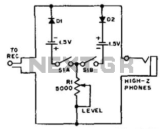
For use with headphones, this circuit sets the audio clipping level via a 5-kOhm potentiometer. This type of noise clipper is most effective for pulse-type noise with a low duty cycle, such as ignition noise. The resistor Rl establishes...