
simple voltage doubler

The described circuit utilizes a NE555 timer integrated circuit (IC) configured to function as a voltage doubler. The primary objective is to increase the input voltage, achieving an output that is approximately double the input voltage, although the output current is limited. The circuit's design incorporates several components with specific tolerances to ensure stable operation.
The NE555 timer (U1) is central to the circuit's functionality, operating in astable or monostable mode, depending on the connections of resistors and capacitors. In this application, it likely operates in astable mode to generate a square wave output, which is then processed to achieve voltage doubling.
Resistor R1 (2.2 kΩ) and resistor R2 (15 kΩ) are fundamental for setting the timing characteristics of the NE555 timer. The values of these resistors determine the frequency of the output waveform, which is critical for the effective operation of the voltage doubling mechanism. Both resistors have a tolerance of 5 to 10 percent and are rated for 1/4 watt, ensuring they can handle the power dissipation without overheating.
Capacitor C1 (0.01 µF ceramic) is used for stability and noise filtering in the circuit. It helps to smooth out any high-frequency noise that may be present, ensuring that the NE555 operates reliably. Capacitors C2 and C3 (220 µF electrolytic) serve as energy storage elements in the voltage doubling process, while capacitor C4 (470 µF electrolytic) provides additional smoothing of the output voltage, reducing ripple and enhancing the stability of the output voltage level.
The overall design of this circuit is straightforward yet effective for applications where a doubled voltage is required, albeit with the limitation of low output current. The choice of components and their respective tolerances is essential to maintain performance and reliability in various operating conditions.this circuit rougly doubles the voltage of the input, however the current output is low. doubled output is at `V source.` all resistors are 5 or 10 percent tolerance, 1/4-watt all capacitors are 10 percent tolerance. U1 NE555 timer IC R1 2.2k ohm resistor R2 15k ohm resistor C1 0.01 uF ceramic capacitor C2, C3 220 uF electrolytic capacitor C4 470 uF electrolytic capa 🔗 External reference
Related Circuits
This device generates high-voltage pulses that disrupt muscles and the nervous system, causing mental confusion in anyone who comes into contact with it. It can be utilized against aggressive animals or attackers; however, it is important to note that...
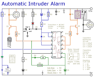
This is a simple single-zone burglar alarm circuit. Its features include automatic exit and entry delays and a timed bell/siren cut-off. It is designed to be used with the usual types of normally-closed input devices such as magnetic reed...
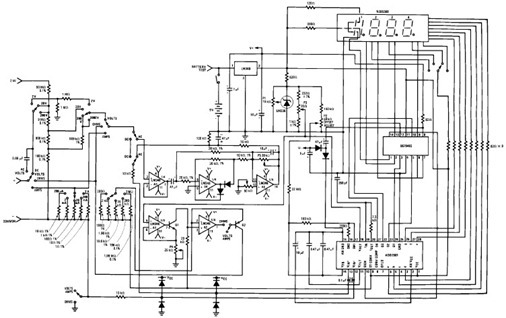
The following circuit illustrates the design of a simple digital multimeter circuit diagram. This circuit employs the ADD3501. Features include the combination of voltage measurements, among others. The circuit design for a simple digital multimeter utilizing the ADD3501 integrates several...
Figure 1 shows the circuit. A major change from all of the designs from that era is the speaker coupling capacitor - 1000uF (for a -3dB of 20Hz and a 8 Ohm load) was the most common value. This is...
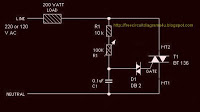
The circuit operates by adjusting the firing angle of the Triac. Resistors R1, R2, and capacitor C2 are involved in this process. The firing angle can be modified by changing the value of any of these components, with R1...

Consider a capacitor with capacitance C that charges to a voltage V and discharges to 0V at a frequency of 5 times per second. To estimate the average current, also referred to as the RMS current, a rough approximation...