
Simple water detector circuits

The water detector circuit is designed to monitor the presence of water or other conductive liquids. The use of alternating voltage is crucial as it minimizes the risk of corrosion on the electrodes, enhancing the longevity and reliability of the sensor. The Schmitt trigger (N1) serves as a signal conditioning component, generating a stable AC signal that is essential for the operation of the circuit.
When moisture is detected between the electrodes, the conductive path allows current to flow, which is rectified by diodes D1 and D2. This rectification process converts the AC signal into a DC voltage, which is then used to charge capacitor C4. The charge on C4 can be monitored to determine the presence of water. If the voltage across C4 exceeds a certain threshold, it can trigger additional circuitry, such as an alarm or a relay, to indicate water presence.
The design of the circuit should also include appropriate values for the resistors and capacitors to ensure sensitivity and stability. The choice of diodes is important; they should have a low forward voltage drop to ensure efficient rectification. Additionally, the layout of the circuit should minimize noise and interference, which can affect the performance of the water detection system.
Overall, this water detector circuit serves as an effective solution for applications requiring moisture detection, such as leak detection systems, agricultural monitoring, and various industrial processes. The simplicity of the design allows for easy implementation and customization based on specific requirements.This simple water detector circuit uses alternative voltage in order to prevent the corrosion of the electrodes. It is easy to build and uses N1 as a trigger Schmitt gate which generate the AC. If between the electrodes is a electricity conductor, for example an aqueous solution, then because of the rectification action of D1 and D2, the C4 capacitor is char..
🔗 External reference
Related Circuits
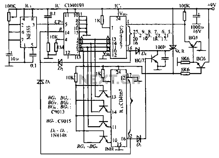
The circuit consists of an oscillator, a counter, and an Iseki circuit divided into three parts. The oscillator is based on the NE555 timer and several external RC components, generating a pulse signal for the counter. The instantaneous power...
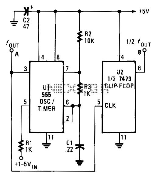
The output frequency of the voltage-controlled oscillator (VCO), U1, varies inversely with the input voltage. With a 1 V input, the oscillator output frequency is approximately 1500 Hz; with a 5 V input, the output frequency decreases to around...
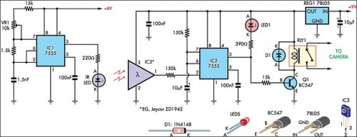
The IR detector (IC3) controls an LM 7555 CMOS timer (IC2) operating in monostable mode. When the beam is interrupted, IC2 is triggered, and its pin 3 output goes high for approximately half a second. This action extinguishes LED1...
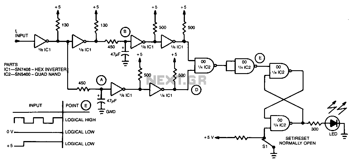
A simple inverter and NAND gate can be connected to create a highly compact and reliable digital frequency detector. This circuit is capable of detecting frequencies up to 3 MHz with a 50% duty cycle. When a frequency appears...
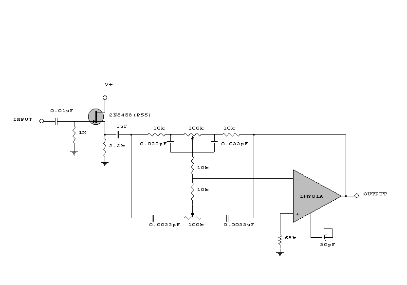
This circuit is a simple series tone control circuit. It utilizes the surgical amplifier LM301A. The JFET 2N3684 provides high input impedance and low noise for the unbuffered operational amplifier, which operates in an equalizer (EQ) configuration. Further details...
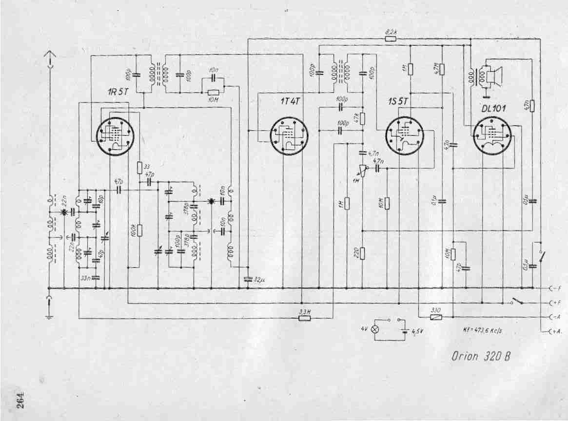
Create a repository of circuits and service data for vintage valve and transistor radios. While many resources are available online, they often come at a cost. The intention is to share circuits and manuals with others rather than profit...