
Simplest atmega8 programmer Using LPT Port

The Atmega 128 microcontroller is a versatile component within the AVR family, known for its in-system programming capabilities that facilitate firmware updates without the need for physical removal from the circuit. To establish a direct programming interface with the LPT port, a basic understanding of the required connections is essential. The key pins involved include Ground (GND), Serial Clock (SCK), Master In Slave Out (MISO), Master Out Slave In (MOSI), and Reset (RESET).
In a typical setup, the GND pin of the Atmega 128 should be connected to the GND of the LPT port to ensure a common reference voltage. The SCK pin is responsible for synchronizing the data transfer, while the MISO and MOSI pins handle the data exchange between the microcontroller and the programming software. The RESET pin is crucial for initiating the programming mode of the Atmega 128.
While the circuit can function without the protective resistors, it is advisable to include 220Ω resistors in series with the SCK, MISO, and MOSI lines. This precautionary measure mitigates the risk of overcurrent conditions that could damage the LPT port or the microcontroller itself. The resistors act as a buffer, limiting the current flowing into the pins during programming operations.
For power supply, a stable 5V (Vcc) is required to operate the Atmega 128. This voltage must be supplied from a reliable source to ensure that the microcontroller functions correctly during the programming process. The PonyProg software, which is commonly used for programming AVR microcontrollers, requires specific settings to be configured for successful communication with the Atmega 128. Ensuring that these settings are accurate is critical for the programming process to proceed without errors.
In summary, programming the Atmega 128 directly through the LPT port is a feasible approach that can be executed with minimal external components, provided that the necessary connections are made carefully, and protective measures are observed. This method allows for efficient updates to the microcontroller's firmware while maintaining the integrity of the programming interface.Atmega 128 is like other AVR microcontrollers. They are ISP is in-system programmable. Earlier I wrote an article about AVR ISP programmer where 74HC244 buffer is used. Using buffer is safer for your AVR. But what if you need 128 atmega programmer without any parts, then you can connect your microcontroller directly to LPT port or use protecti on resistors (220R) just in case. of course circuit works without resistors, but you put your LPT port at risk. Just connect GND, SCK, MISO, MOSI and RESET to adequate LPT pins and you can program atmega`s flash memory without removing it from socket. Programming software can be PonyProg. you also need power supply 5v Vcc For IC. if you Using PonyProg make sure the setting like this. 🔗 External reference
Related Circuits
An oscillator circuit is an electronic circuit that produces a periodic signal. The term quadrature refers to a fourth (1/4) phase shift of a full wave cycle (1/4 of... An oscillator circuit is a fundamental component in various electronic systems,...
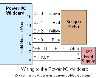
For optimal efficiency, set MAX_STEPPERS to the number of stepper motors being controlled, with a maximum limit of four. Motors are identified by indices 0, 1, 2, and 3. On the QCard, there is a trade-off between the number...
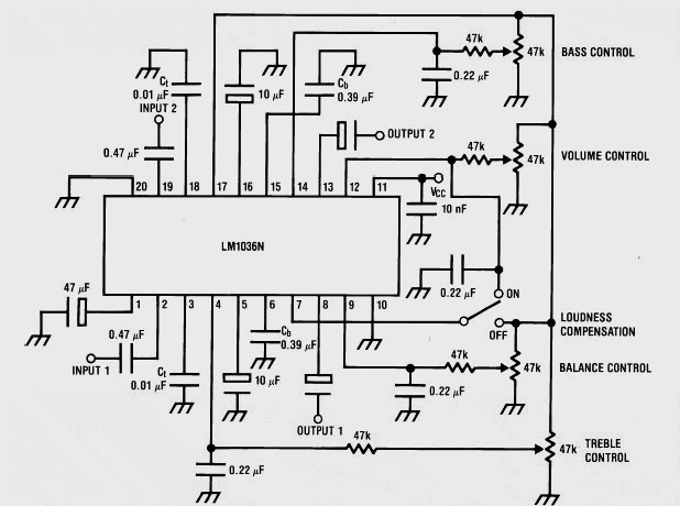
This weblog discusses electronic circuit schematics, PCB design, DIY kits, and electronic project diagrams. It features a stereo tone control circuit built using the LM1036 integrated circuit (IC). This control circuit adjusts bass, treble, volume, and the balance between...
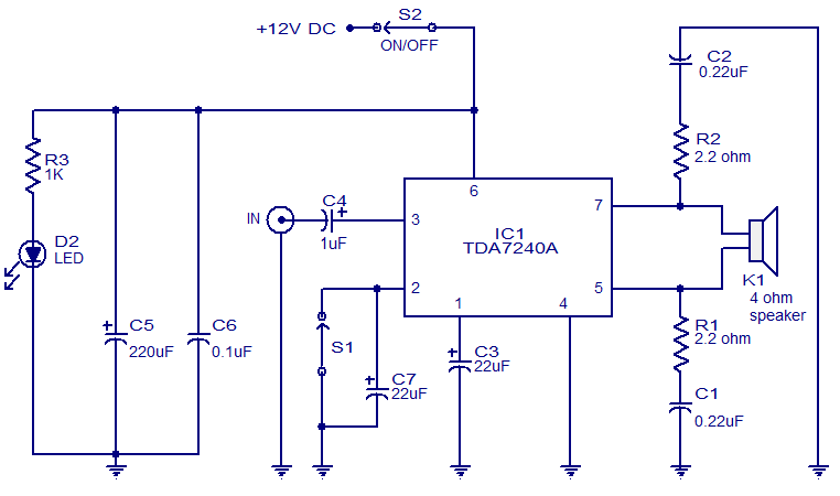
The audio amplifier presented here is based on the TDA7240 integrated circuit from ST Microelectronics. The TDA7240 is capable of delivering 20 watts of audio output power into a 4-ohm load. It requires a minimal number of external components...
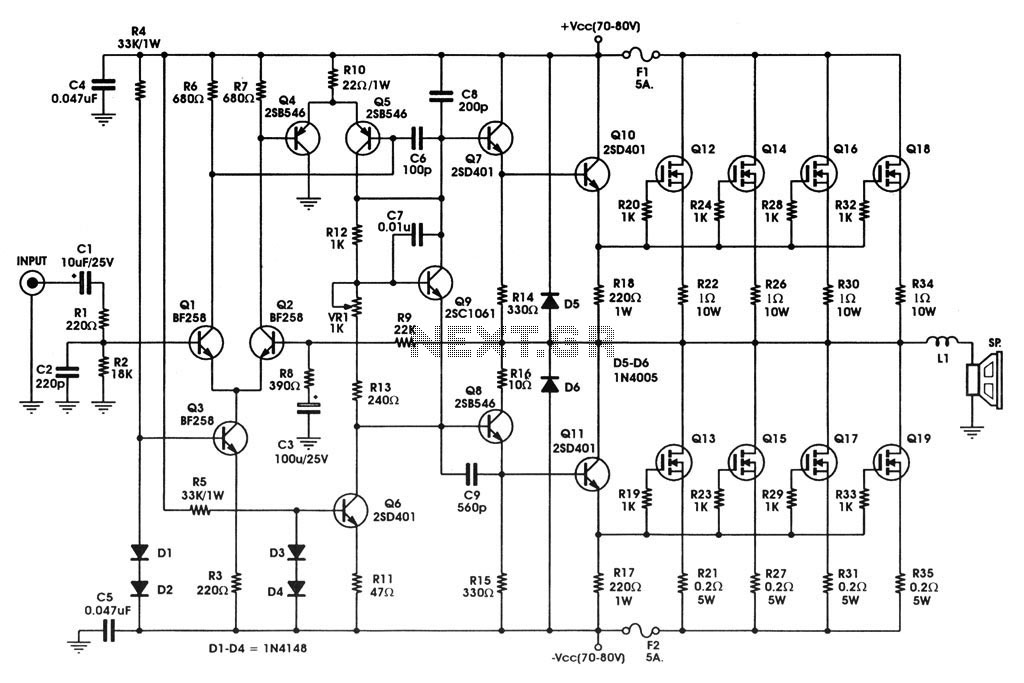
400 W MOSFET Audio Amplifier circuit using IRFP448. This circuit is categorized under amplifiers and includes five circuit diagrams. For more detailed information, refer to the main post titled "400 W MOSFET Audio Amplifier Using IRFP448." This post also...
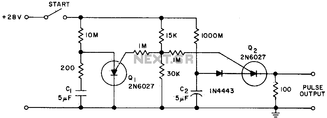
The Programmable Unijunction Transistor (PUT) serves as both a timing element and a sampling oscillator. A low leakage film capacitor is required for capacitor C2 because of the minimal current supplied to it. The Programmable Unijunction Transistor (PUT) is a...