
Four lighting sound and light control switch circuits

The described circuit utilizes a resistor and capacitors in conjunction with a thyristor to create a delay mechanism for lamp activation. In this configuration, resistor R8 plays a critical role in controlling the charging time of capacitor C4. As the circuit is powered, C4 begins to charge through Rs, which sets the time constant for the delay. The time constant is calculated based on the values of Rs and the capacitance of C4, which collectively dictate how long it takes for the voltage across C4 to reach the thyristor's gate trigger voltage.
Once the voltage across C4 reaches the required threshold, the thyristor conducts, allowing current to flow to the lamp and illuminating it. The delay time can be adjusted by changing the values of Rs or C4, allowing for flexibility in application. The inclusion of capacitor Cd serves as a filtering component, providing stability and reducing noise in the circuit, ensuring reliable operation of the thyristor switch.
In summary, this circuit effectively uses the principles of RC timing to create a controlled delay for lamp activation, making it suitable for applications requiring timed lighting solutions.A resistor R8, capacitors Cd and thyristor V AC switch delay composition. Lamp lighting delay time is determined by Rs, C4. Press the component parameters as shown in Figure 2- 114, the delay of approximately 40s.
Related Circuits
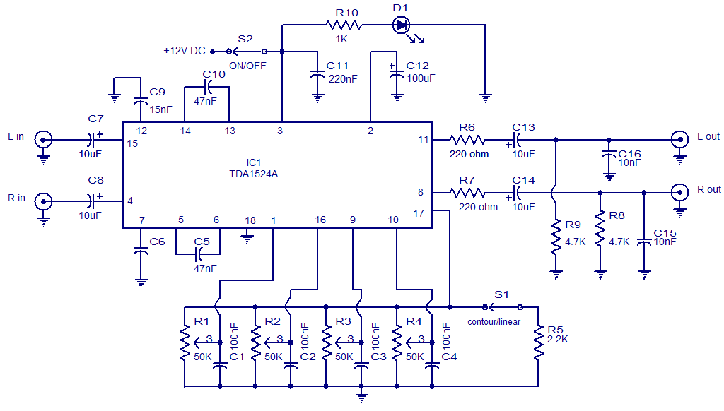
The circuit diagram presents a high-quality stereo preamplifier featuring tone control, utilizing the TDA1524 IC from Philips. This integrated circuit requires minimal external components, operates with low noise, and accommodates a broad power supply voltage range. Potentiometers R1 through...

This circuit is straightforward yet valuable, providing a high-quality interior light delay feature. This feature is standard in most modern vehicles, though the automatic dimming version is typically found in higher-end models. This circuit allows for the enhancement of...
TI's Dafydd Roche concludes his 4-part series on soundbar design with a thorough explanation of clock design for the digital section of the circuit. The clock design in digital circuits, particularly in soundbar applications, plays a crucial role in ensuring...
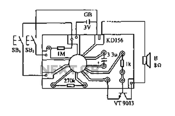
The analog sound KD156 produces a lingering "Ding Dong" sound reminiscent of birds singing, utilizing an integrated circuit. The KD156 is an analog sound generator designed to replicate natural soundscapes, particularly the soothing and familiar tones of birds singing. The...

As the only electronics engineer in the family and circle of friends, it is sometimes challenging to decline requests for assistance. Recently, a friendly elderly lady in a retirement home sought help regarding her lighting situation. In her room,...
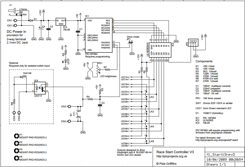
The circuit described on this page is designed around Kingbright's 52mm LED cluster module which comprises 50 red LEDs in a waterproof housing with a brightness in excess of 16000mcd. In the original version of this project each LED...