
Automatic Garden Lamp Simple Electronic Circuit Schematic for Turn-on and Turn-off Lamp Automatically

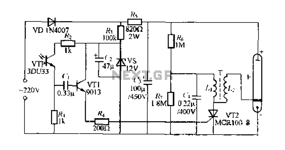
This circuit is designed to provide an automatic lighting solution based on ambient light conditions, utilizing a light-dependent resistor (LDR) and a silicon-controlled rectifier (SCR). The LDR (R2) acts as a sensor that detects light levels; its resistance decreases in bright conditions and increases in darkness. This change in resistance affects the voltage at the gate of the SCR, which controls the flow of current to the connected lamp.
The configuration of R1 and R2 as a voltage divider is crucial for setting the appropriate threshold for the SCR to trigger. By adjusting R1, the sensitivity of the circuit can be fine-tuned to ensure that the lamp operates correctly under various lighting conditions. If the LDR detects darkness and the voltage at the gate exceeds the SCR's threshold, the SCR will conduct, allowing current to flow to the lamp and illuminating it. Conversely, when the ambient light increases, the resistance of the LDR decreases, lowering the voltage at the gate and turning off the SCR, thus extinguishing the lamp.
The SCR's ability to operate at a DC voltage of 220V makes it suitable for directly controlling high-voltage lamps, providing a reliable solution for outdoor lighting applications. The design allows for an efficient and automatic response to changing light conditions, enhancing energy efficiency and convenience.
For users interested in customizing the circuit, the availability of original schematic and PCB layout files facilitates modifications. The use of PCB Wizard software not only supports the design process but also allows for easy adjustments and optimizations of the layout, ensuring that the final product meets specific requirements. The auto-route feature in PCB Wizard simplifies the layout process, making it accessible even for those with limited PCB design experience.Adjust value of R1 to get good performance of sensor LDR, if in your practice with 2. 2 M ohm still turn on the lamp you can add value of R1 with the large of 2. 2 M ohm. R1 and R2 is used as voltage divider. R2 is LDR that resistance will change when LDR in the dark or bright condition. And then it will change voltage in R2 as input of gate SCR or thyristor. If VR2 is too small SCR will close circuit and VR2 is high SCR will open circuit. SCR or Thyristor is operated with DC voltage 220 DC and will operate like electronic switch with triggered from gate. SCR will open and close depend of voltage from gate terminal. If the circuit and schematic connected with lamp (bulb lamp) and source voltage 220 VAC it will make lamp turn-on and turn-off automatically depend of dark or bright condition.
If you interesting with this circuit schematic of automatic garden lamp and want to modified the schematic or PCB layout, we provide you original file of Schematic and Layout PCB that you can download freely. To open this file you can use PCB Wizard software, because we design schematic and PCB layout using PCB Wizard.
Figure 3 is sample of PCB Layout that we generated using auto route from PCB Wizard. You also can take Free Download Software PCB Wizard from here. 🔗 External reference
Related Circuits

This simple tone control (bass and treble control) can be utilized in various audio applications. It can be integrated into amplifiers, function as a standalone control module, or even be incorporated into new and innovative instruments. The circuit employs...
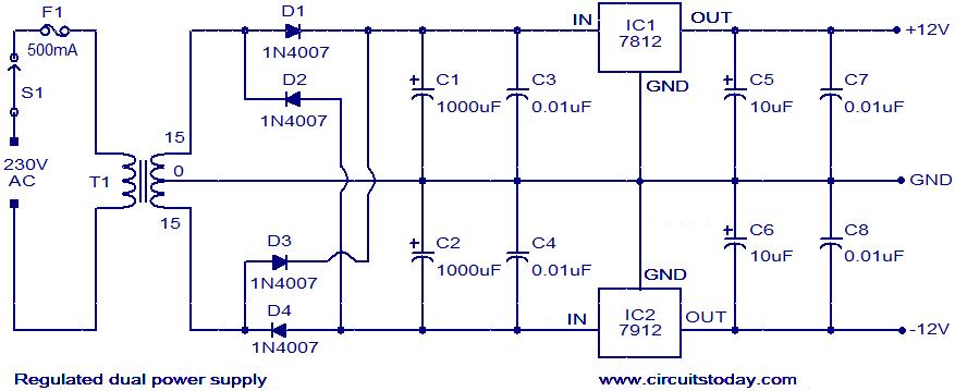
The circuit described is a regulated dual power supply that provides +12V and -12V from the AC mains. Such a power supply is an essential tool for electronic hobbyists. The transformer T1 reduces the AC mains voltage, while diodes...
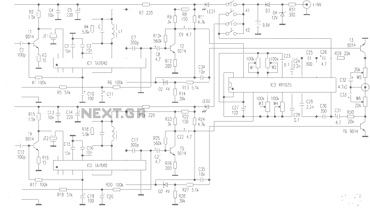
The production of high-quality wireless microphones is a common aspiration among enthusiasts, but achieving a high-performance receiver is challenging. This project explores the use of salvaged FM radio cassette players to enhance an XR1075 audio processor, leading to the...
Connect the two sections of the variable capacitor (C3) in series to linearize the tuning somewhat. Use the connections on either end of C3 and do not use the middle lead. The gain is sufficient to drive an earphone....

12V Battery Charge Nominal Discharge (Low) Indicator Circuit. This circuit monitors car battery voltage and provides an indication of nominal supply voltage, as well as low or high voltage. The 12V Battery Charge Nominal Discharge Indicator Circuit is designed to...
Engaged in indoor portrait photography, practitioners often find that using a single camera can result in images lacking depth and layering. To achieve better photographic outcomes, multiple auxiliary lighting sources are typically arranged around the subject. The following describes...