
sine wave generation with fast pwm mode 2525

The implementation of sinusoidal pulse width modulation (SPWM) for sine wave generation in an inverter application involves several critical components and configurations. The choice of microcontroller, in this case, the ATMEGA16, is pivotal due to its integrated PWM capabilities. The oscillator frequency of 16MHz allows for sufficient resolution in generating the SPWM signals, while the selected switching frequency of 16kHz ensures that the output waveform is smooth and suitable for AC applications.
The use of the Fast PWM mode enables efficient control of the duty cycle, which is essential for accurately reproducing the desired sine wave shape. By setting ICR1 as the TOP value and using a prescaler of 1, the PWM frequency is optimized for the application. The configuration of TCCR1A and TCCR1B registers is crucial as it defines the operational mode and the behavior of the output compare function.
The sine table, generated with a peak value of 990, is a vital element in the SPWM generation process. The inclusion of zeros at the beginning and end of the table serves to create necessary deadtime, which is critical in preventing short circuits caused by simultaneous conduction of the high and low side MOSFETs. This deadtime is particularly important in high-frequency switching applications to ensure reliable operation of the inverter.
The mechanism for directing the PWM signals to the appropriate MOSFETs through the "Direction" bit and the use of AND gates illustrates a clever hardware solution to manage the output stages of the inverter. This design allows for flexibility in controlling the output phase, facilitating the generation of a balanced AC waveform.
Overall, this approach to generating sine wave outputs using SPWM with an AVR microcontroller exemplifies the versatility of PWM technology in power electronics applications, providing a foundation for further exploration and adaptation in various microcontroller environments.Generate sinusoidal pulse width modulation (SPWM) signals using the ECCP module in a PIC for generating a sine wave output for use in DC-AC inverter. I have had requests from people asking how to generate the same SPWM signals with other microcontrollers that don`t have the ECCP module, such as the super popular PIC16F877A.
And so I had written another article where I showed how to generate sine wave using SPWM with the CCP module of a PIC. This concept, as I had mentioned in that tutorial, can be extended to use for any microcontroller that has a PWM module. And so, I`ve decided to demonstrate how to generate sine wave using SPWM with an Atmel AVR microcontroller.
The microcontroller I`ve chosen is the ATMEGA16. However, the concept can be used on any AVR that has a PWM module. The output sine wave is to have a frequency of 50Hz. I have chosen to use a switching frequency of 16kHz for SPWM. So, here I talk about how to generate sine wave using sinusoidal pulse width modulation (SPWM) signals using the PWM module as can be commonly found on most Atmel AVR microcontrollers. If you`re curious regarding my previous tutorials that revolved around the Microchip PIC microcontrollers, you should go through the other articles related to generating SPWM to get an idea of what I`m talking about regarding sine wave generation: Below (Fig.
2) is the circuit diagram for the configuration of the MOSFETs and the drivers - and the synchronization with the signals generated from Fig. 1 above. Here, I`ve used the Fast PWM mode. I chose to use an oscillator frequency (for ATMEGA16) of 16MHz and an SPWM switching frequency of 16kHz.
For this, I selected ICR1 as the TOP and assigned 999 to ICR1. I used a prescaler divider (N) = 1. I used PWM mode 14. So that gives a switching frequency of: I`ve assigned 0x82 to TCCR1A and 0x19 to TCCR1B. This sets PWM mode to mode 14. This also sets Compare Output mode for OCR1A to non-inverting mode: Clear OCR1A on compare match, clear at BOTTOM. I have selected the sine table such that the peak value is smaller than TOP. To generate the sine table, I used my software Smart Sine with a peak value of 990. Also notice how there`s a zero at the beginning and ending of the sine table. These act to create a deadtime so that there isn`t a short circuit due to cross-conduction between the MOSFETs in the same leg being driven.
I did this by generating a sine table with 31 values and a peak of 990 and then adding a zero at the end. See Fig. 5 below for demonstration of the deadtime. For my software "Smart Sine", visit this page: The SPWM generation is done by the single PWM module and which MOSFETs to send the signals to is set by the "Direction" bit and the hardware trick employing the AND gates.
When "Direction" is equal to 0, the high side MOSFET A is kept on for 10ms during which time the SPWM signals on PWM (OC1A) output (PORTD5) are sent to low side MOSFET D by sending a "1" to PORTD3, which, with the help of the AND gate "diverts" the OC1A signal to the low side MOSFET D (see Fig. 1 above). The same thing is achieved when "Direction" is equal to 1, just with high side MOSFET C and low side MOSFET B.
When MOSFETs A and D are operated, MOSFETs B and C are kept off and vice versa. For MOSFET drive, we need 4 pins for the 4 drive signals and I`ve chosen PORTD bits 0 to 3. I`ve arbitrarily chosen these four pins but you can choose any four pins really. The MOSFETs are first turned off before the other two are turned on, as can be seen in the code block: When Timer/Counter 1 reaches TOP, TOV1 flag is set and since interrupt is enabled, the ISR in the corresponding interrupt vector is served. There table pointer is made use of to retrieve the required values off the sine table and assign them to OCR1AH and OCR1AL the 16-bit resultant in OCR1A sets the duty cycle.
The sine table stores the duty cycle in such a way that when th 🔗 External reference
Related Circuits
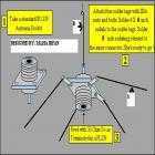
This Antenna is most widely used all over the world. For example, when you see a police car it has a transmitter with Ground Pole Antenna. The body of the car serves as ground. It accepts load from a...
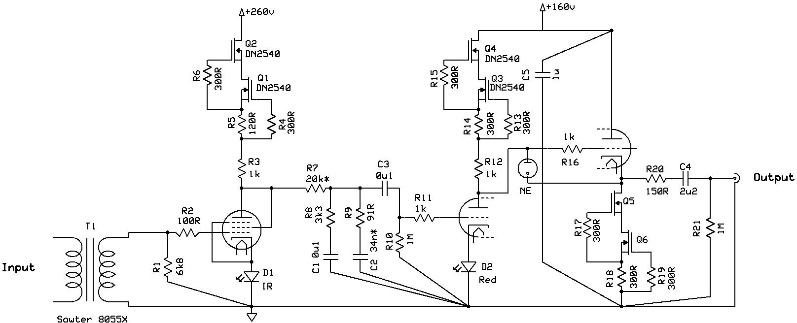
Even if it was not read thoroughly, it is a nice design with almost enough transformers, but certainly not enough shunt regulators. The circuit design under consideration features a configuration that includes several transformers, which are essential for voltage transformation...
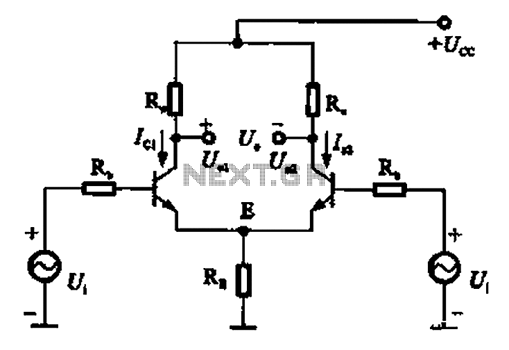
The common mode signal of an emitter-coupled differential amplifier circuit assumes that two equal small increases of the same polarity signal, referred to as the common mode signal, occur simultaneously. This results in an increase in the potential at...
The form of a musical signal never resembles a square wave. The frequency range perceived by an average adult rarely exceeds 17 kHz. Therefore, the appropriateness of testing audio amplifiers with a 100 kHz square wave signal is often...

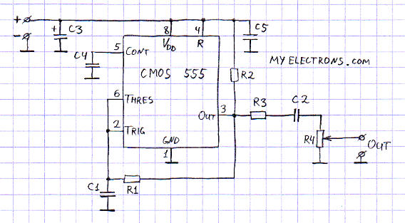
This free-running square-wave oscillator utilizes two NPN transistors. The output frequency is approximately 300 Hz with the specified component values. The circuit operates as a basic oscillator, generating a square wave output through the interaction of two NPN transistors. The...

This generator circuit utilizes an overdriven amplifier to generate a 60 Hz square wave from the 60 Hz AC line. The circuit is suitable for line-operated applications as a clock source. The generator circuit operates by leveraging an overdriven amplifier...