
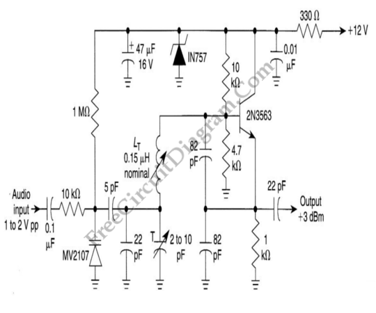
Sine Wave Oscillator Circuit Using Phase Shifter

The Wien-Bridge oscillator is a type of electronic oscillator that generates sine waves. It is based on a bridge circuit consisting of resistors and capacitors, which allows for the generation of a stable frequency output. The circuit typically includes an operational amplifier (op-amp) to provide the necessary gain and feedback.
In a Wien-Bridge oscillator, two resistors and two capacitors form the bridge. The resistors are usually equal in value, and the capacitors are also equal, which helps to set the frequency of oscillation. The frequency (f) of the output sine wave can be calculated using the formula:
f = 1 / (2πRC)
where R is the resistance and C is the capacitance used in the circuit. A common feature of the Wien-Bridge oscillator is its ability to maintain amplitude stability through the use of a light bulb or thermistor in the feedback loop, which automatically adjusts the gain of the op-amp to prevent distortion.
The circuit can be configured for various frequencies by selecting appropriate values for the resistors and capacitors. Additionally, the use of an op-amp allows for a more compact design and the ability to drive loads directly without the need for additional amplification stages.
For practical applications, the Wien-Bridge oscillator is widely used in audio signal generation, function generators, and as a test signal source in various electronic devices. Its simplicity and effectiveness make it a popular choice for generating high-quality sine waves in laboratory and industrial environments.Sine wave oscillator can be implemented using Wien-Bridge oscillator like in our previous sine wave oscillator circuit, but now we present another method of. 🔗 External reference
Related Circuits
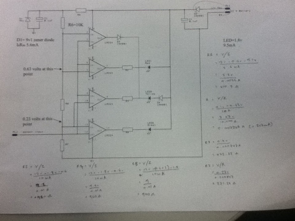
The diagram illustrates the connections for the inputs and outputs of each operational amplifier from the power source, detailing how each operational amplifier is configured to operate individual light-emitting diodes (LEDs). It also includes calculations for determining each resistor...
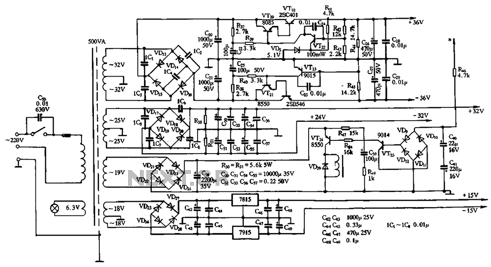
The power supply circuits for servo systems are critical during both the adoption and operational stages. The power supply circuit for servo systems is designed to provide stable and adequate voltage and current levels necessary for the servo motors to...
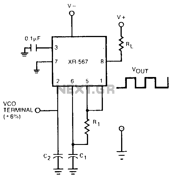
The oscillator output of the XR-567 can be amplified using the output amplifier and high-current logic output available at pin 8. In this manner, the circuit can switch 100-mA load currents without sacrificing oscillator stability. The oscillator frequency can...

This is a design circuit diagram of a versatile FM transmitter. This circuit does not include a coil and is simple and easy to assemble. It operates based on gate logic concepts. The circuit features a buffer gate N1...
One of the simplest methods of metal detection is through a beat frequency oscillator. The circuit consists of two balanced oscillators: one provides a reference signal, while the other acts as the detector element. The frequency of the reference...
An oscillator can be constructed using an LC (inductor-capacitor) tank circuit. By varying the capacitance of the capacitor in the LC tank circuit, the frequency of the oscillator can be adjusted. An LC tank circuit serves as a fundamental building...