
Frequency Modulated Oscillator (for FM Transmitter)
")
An LC tank circuit serves as a fundamental building block for oscillators, utilizing the resonance between an inductor (L) and a capacitor (C) to generate oscillations. The resonant frequency (f) of the circuit can be calculated using the formula:
f = 1 / (2π√(LC))
where L is the inductance in henries and C is the capacitance in farads. By adjusting the capacitance of the capacitor, the resonant frequency can be tuned to the desired value, allowing for precise control over the output frequency of the oscillator.
In practical applications, the LC tank circuit is often combined with active components such as transistors or operational amplifiers to provide the necessary gain and ensure sustained oscillations. The inductor and capacitor are typically connected in parallel or series configuration, depending on the specific oscillator design.
Additionally, the quality factor (Q) of the tank circuit plays a crucial role in determining the stability and sharpness of the oscillation frequency. A higher Q factor indicates a lower rate of energy loss relative to the energy stored in the circuit, resulting in a more stable oscillation.
Overall, the LC oscillator is widely used in various electronic applications, including radio frequency transmission, signal generation, and clock generation in digital circuits. Its simplicity and effectiveness make it a popular choice in both educational and professional electronic design.An oscillator can be built using LC (inductor-capacitor) tank circuit. When we vary the capacity of the capacitor in LC tank circuit then the frequency of the.. 🔗 External reference
Related Circuits
Most frequency multiplier circuits utilize an integrated circuit (IC) phase-locked loop (PLL). These circuits typically increase the frequency by an integer factor only. However, this particular circuit is capable of doubling the frequency. Frequency multiplier circuits are essential in various...
A 52 MHz third overtone crystal typically has a series resonance impedance of 30 ohms as per manufacturer specifications. The crystals utilized in the prototypes exhibit nearly ten times lower series resistance but are significantly more expensive. An oscillator...
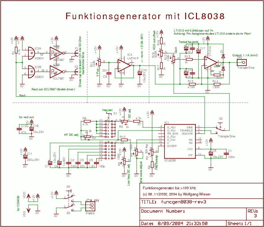
The circuit design is relatively straightforward. It features a Voltage Controlled Oscillator (VCO) utilizing the ICL8038 along with supplementary components, a sine and triangle output stage using the LT1210, and a CMOS-compatible output stage driven by the MOSFET driver...
Rf = 100 k preset. The slider is positioned approximately a quarter of the way around. This component is utilized to control the gain, which should be minimized while ensuring the oscillator starts reliably. Zener diodes limit the oscillator...
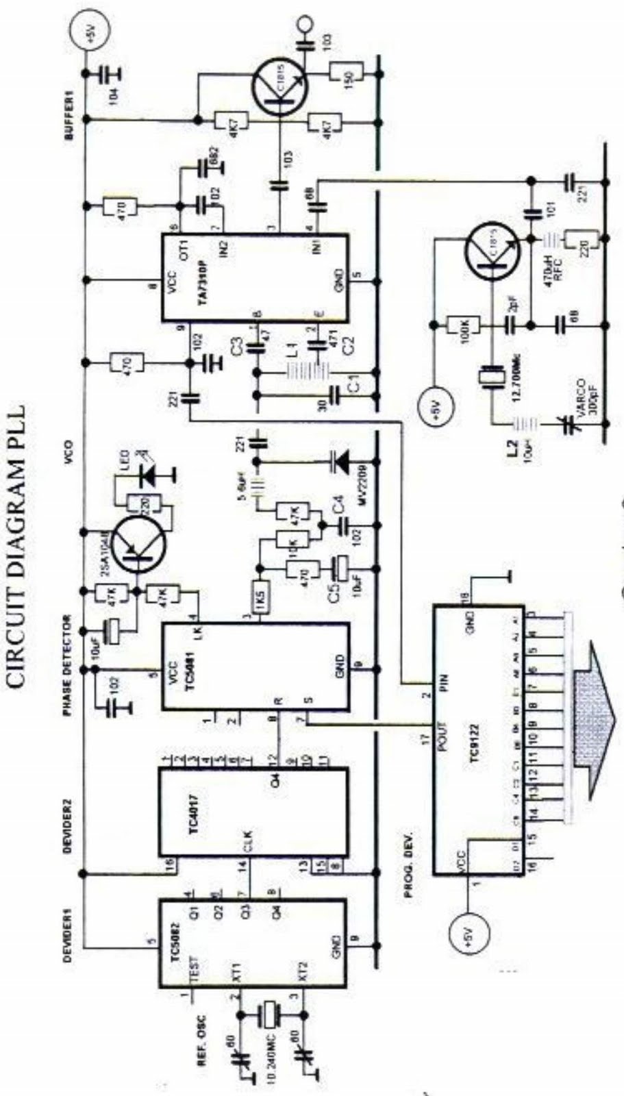
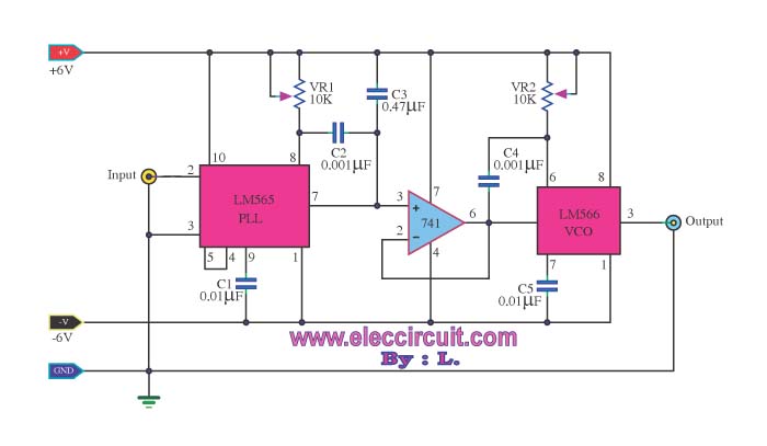
The primary function of the phase-locked loop (PLL) phase detector is to compare the input phase of the voltage-controlled oscillator (VCO) signal with a reference signal, resulting in a phase difference. This phase difference generates a voltage difference, which...
The most popular network is MED-NET, which encompasses the entire Mediterranean Sea with its observation points. The accompanying map illustrates these observation points. For more information about this network, which is part of the Italian Geophysical National Institute, the...