
Shortwave fet booster

The two-transistor preselector circuit is designed to amplify signals within the frequency range of 3 to 30 MHz, achieving a gain of up to 40 dB. This circuit typically utilizes two transistors, often configured in a common-emitter or common-source arrangement to maximize gain while maintaining stability across the specified frequency range. The choice of a MOSFET for Q1 is particularly advantageous due to its high input impedance and low noise characteristics, which are essential for preserving signal integrity in RF applications.
The design must incorporate appropriate biasing resistors to ensure that the transistors operate in their active regions without distortion. Additionally, coupling capacitors are essential for blocking DC components while allowing AC signals to pass through, thus facilitating the amplification of RF signals.
Careful attention should be paid to the layout of the circuit board, as parasitic capacitances and inductances can significantly affect performance at high frequencies. It is crucial to minimize lead lengths and use short traces to reduce these unwanted effects.
Moreover, the sensitivity of Q1 to static charges necessitates the implementation of ESD (Electrostatic Discharge) protection measures. This can include the use of grounded conductive mats during assembly and the incorporation of protective components, such as diodes, to safeguard the MOSFET from potential damage.
Overall, this two-transistor preselector is an effective solution for enhancing signal levels in the specified frequency range, provided that proper handling and circuit design practices are observed.This two transistor preselector provides up to 40 dB gain from 3 to 30 MHz Ql (MOSFET) is sensitive to static charges and must be handled with care.
Related Circuits
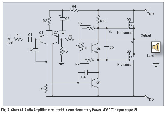
Utilizing the latest advancements in trench and polar power MOSFET technologies, both trench and polar P-Channel power MOSFETs have been developed that maintain all the characteristics of comparable N-Channel power MOSFETs, including rapid switching, voltage control, ease of paralleling,...
A mixer can have as many or as few channels as needed by duplicating the input sections shown in the schematic design. An audio amplifier is an electronic device that amplifies low-power audio signals, which primarily consist of frequencies...
This is a driver circuit for a nixie tube. The circuit utilizes the 2N3684 transistor as the nixie tube driver due to its Vp rating of 2-5 volts, which ideally matches TTL-DTL logic levels. The nixie tube driver circuit is...
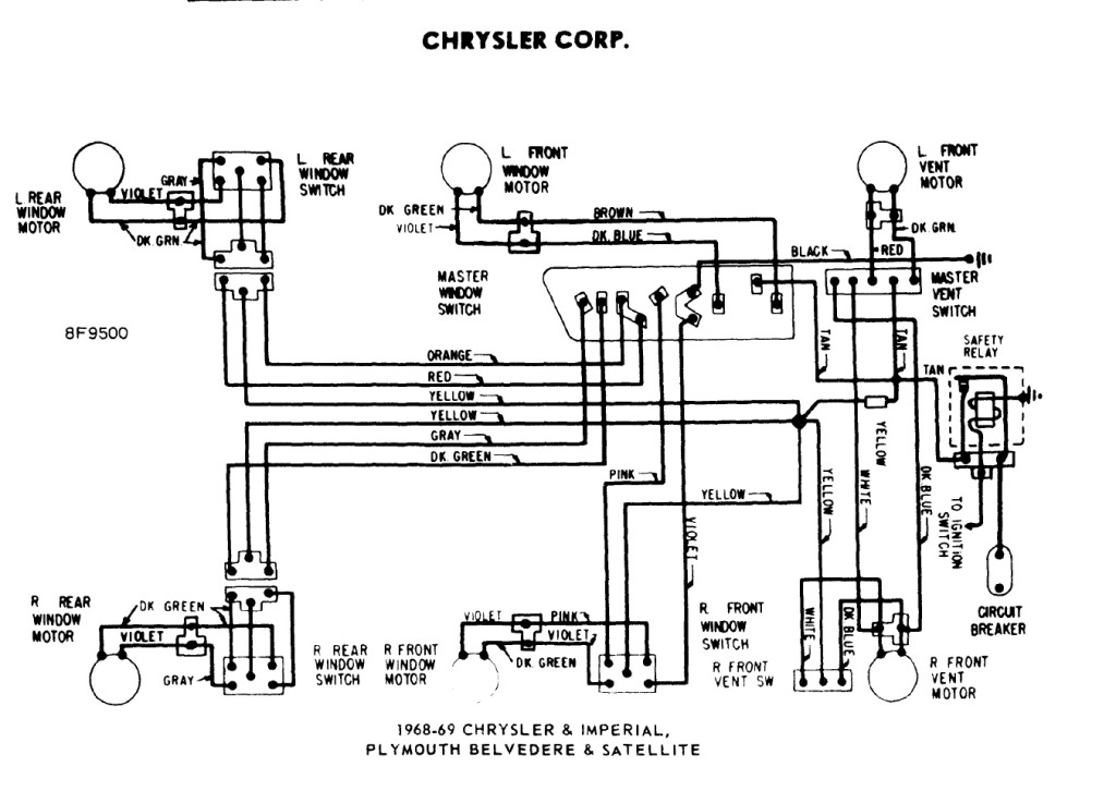
The power windows operate slowly, but connecting 12 volts directly to the motors allows them to function properly. A previous discussion mentioned using a common 5-pin ice cube relay, but there was no confirmation of its effectiveness. The power...
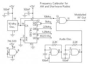
The following circuit illustrates an AM/Shortwave Radio Frequency Calibrator Circuit Diagram. This circuit is based on the 74LS93 IC. Features: The .. The AM/Shortwave Radio Frequency Calibrator Circuit utilizes the 74LS93 integrated circuit, which is a 4-bit binary counter. This...
A JFET-bipolar cascode circuit is designed to deliver complete video output for driving the cathode of a CRT. The configuration offers an approximate gain of 90. The cascode arrangement mitigates issues related to the Miller capacitance of the JFET...