
Sine Wave To TTL Converter

This circuit typically employs a comparator to achieve the conversion from sinusoidal to TTL levels. The sinusoidal input signal is fed into the non-inverting input of the comparator. The inverting input is connected to a reference voltage, which can be set at half the supply voltage for optimal performance.
When the sinusoidal signal exceeds the reference voltage, the comparator outputs a high TTL signal (typically close to the supply voltage, such as 5V for standard TTL). Conversely, when the sinusoidal signal falls below the reference voltage, the output transitions to a low TTL signal (close to 0V).
To ensure proper operation, the circuit may include hysteresis, which helps to prevent false triggering due to noise or small fluctuations in the input signal. This is often implemented by adding a feedback resistor from the output of the comparator back to the non-inverting input, thereby creating a stable operating point.
The circuit can be powered by a dual supply or a single supply, depending on the design requirements. Additionally, the input signal should be AC-coupled through a capacitor to block any DC offset that could affect the performance of the comparator.
Overall, this circuit is suitable for applications where it is necessary to convert analog sinusoidal signals into digital TTL signals for further processing or interfacing with digital logic circuits.As the title implies, the present circuit is intended to convert sinusoidal input signals to TTL output signals. It can handle inputs of more than 100 mV.. 🔗 External reference
Related Circuits
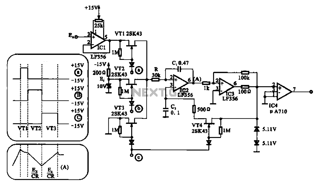
An A/D converter transforms an analog signal into a digital format. Various circuit configurations exist, as illustrated in Figures 21-24, which depict the structure of an A/D converter. One practical circuit configuration utilizes the integrated circuit LF356. The A/D converter...
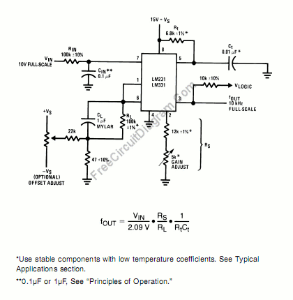
A voltage-to-frequency converter can be constructed using the LM231/331 chip, making it a cost-effective solution for applications such as analog-to-digital conversion and frequency-to-voltage conversion over extended periods. The LM231/331 series of voltage comparators can be effectively utilized to design a...
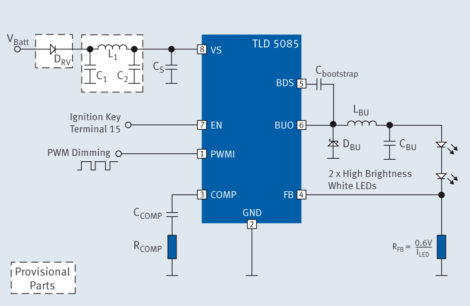
The TLD 5085EJ is a smart LED buck converter featuring an integrated power switch, designed to drive a load current of up to 1.8A with excellent line and load regulation. This device is specifically intended for stepping down input...
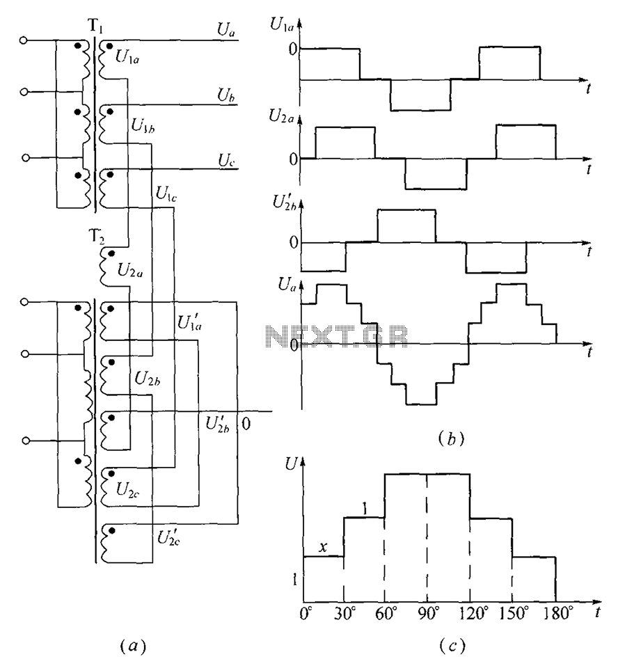
As shown, (a) for the three-phase step wave inverter output transformer winding connections; (b) in the figure, its output waveform. The three-phase step wave inverter is designed to convert direct current (DC) into a three-phase alternating current (AC) output. This...

The circuit employs a field-effect transistor (FET) at the input of a Schmitt trigger, allowing the use of a low-value capacitor. The trigger, controlled by Q1 and O2, exhibits a hysteresis of approximately 3V, regulated by a 3V zener...
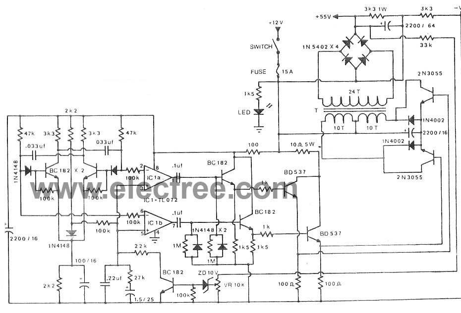
A main component along with a 2N3055 transistor and an IC TL072 is utilized in the pulse oscillator generator. The output voltage reaches +50V and -50V, providing a current of 2A to 3A. The circuit employs a 2N3055 transistor, which...