
Three-phase step wave inverter output transformer winding connection and the output voltage waveform

The three-phase step wave inverter is designed to convert direct current (DC) into a three-phase alternating current (AC) output. This inverter utilizes transformer winding connections to achieve the desired output characteristics. The transformer plays a crucial role in stepping up or stepping down the voltage levels as required by the application.
In the schematic, the winding connections of the transformer are organized to facilitate the generation of a step wave output. Each phase of the inverter is connected to its respective winding, ensuring that the output is balanced and symmetrical, which is essential for the efficient operation of three-phase systems. The output waveform produced by the inverter is characterized by its step-like appearance, which is indicative of the switching mechanism employed in the inverter design.
The output waveform can be analyzed for its fundamental frequency and harmonic content, which are critical for determining the quality of the power delivered to the load. Proper filtering and modulation techniques may be applied to reduce any unwanted harmonics and improve the overall performance of the inverter.
In summary, the three-phase step wave inverter output transformer winding connections are integral to achieving a reliable and efficient AC output, while the output waveform reflects the inverter's operational characteristics and performance. As shown, (a) for the three-phase step wave inverter output transformer winding connections; (b) in FIG its output waveform.
Related Circuits
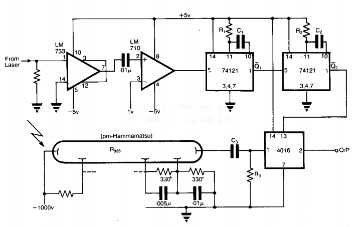
The application involves observing the light pulse emerging from a thick specimen after transillumination by a laser pulse. Pulses derived from the laser source are amplified using a Video Amplifier LM733. The reference level is set to 1 V...
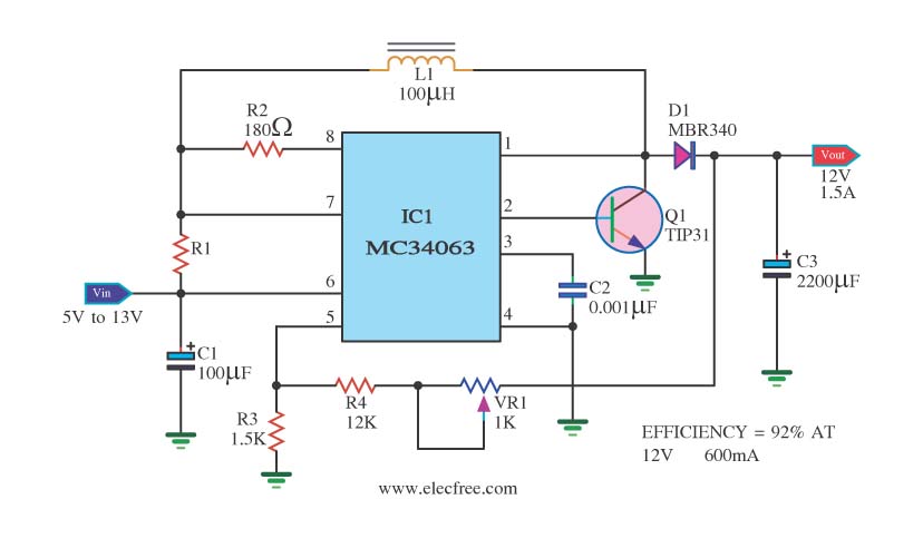
The circuit is a battery-powered voltage regulator that outputs 12V at 1.5A. It accepts an input voltage range from 5V to 13V. The circuit utilizes the MC34063 integrated circuit, making it a straightforward design. The circuit primarily functions as a...
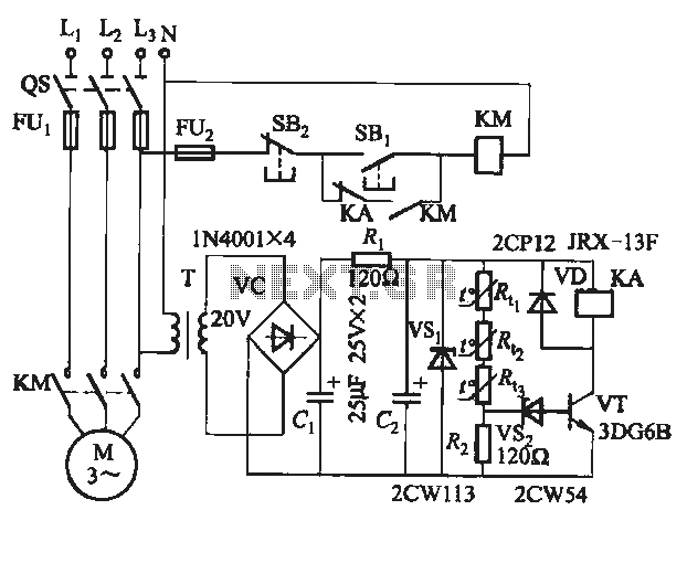
The semiconductor thermistor is an embedded thermal protection element that is sensitive to temperature, with a temperature error of 5 degrees. It offers reliability, a small size (diameter 3.5 mm), and ease of installation, making it suitable for embedding...
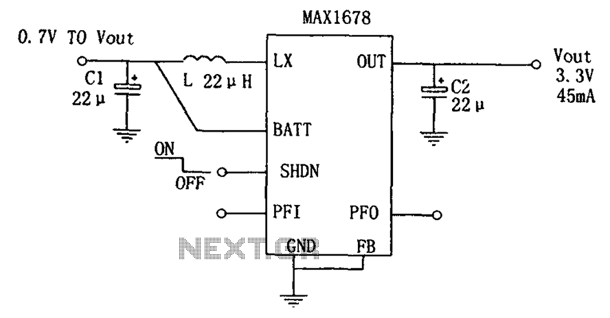
As depicted in the figure, this circuit is suitable for high-efficiency single-cell battery power boosting. It comprises a MAX1678 integrated circuit and three external components. The MAX1678 is designed for low-power applications and features an ultra-small 8-pin MAX package....
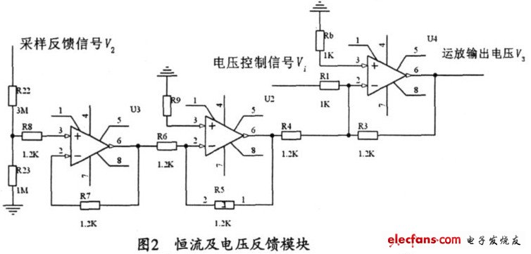
The output current range of the parameter current regulator is limited, and its precision is not high. Connecting the feedback adjustment type output current of the current-stabilized power source in series results in lower efficiency. The steady current source...
A common requirement across various applications is a continuous signal source that produces a regular and definable waveform. Among these waveforms, the square wave is particularly significant. The circuit described utilizes a comparator featuring both positive and negative feedback...