
Single-chip digital voltmeter

The described circuit is a single-chip digital voltmeter (DVM) utilizing the Maxim ICL7129ACPL integrated circuit, which serves as both the analog-to-digital (A/D) converter and the liquid crystal display (LCD) driver. The 4 1/2-digit resolution indicates that the DVM can display values from 0.000 to 19.999 volts with a high degree of precision. The ICL7129ACPL incorporates features such as auto-zeroing and low drift, which enhance measurement accuracy and reliability.
To ensure stable and accurate voltage references, the circuit employs the ICL8069 CCZR, a 1.2-V band-gap reference diode. This component provides a stable reference voltage for the A/D converter, which is crucial for achieving precise voltage measurements. The band-gap reference is designed to maintain its output voltage over a wide range of temperatures and supply voltages, thereby improving the overall performance of the DVM.
The circuit typically includes additional components such as resistors and capacitors for signal conditioning, filtering, and noise reduction. The input stage may consist of a voltage divider to scale the input voltage to the appropriate range for the A/D converter. Furthermore, the LCD driver functionality integrated into the ICL7129ACPL allows for direct control of the display, simplifying the design and reducing the number of external components required.
In summary, this digital voltmeter circuit combines advanced IC technology with precision reference components to deliver accurate and reliable voltage measurements in a compact design, making it suitable for a variety of applications in electronics testing and measurement.Single-chip digital voltmeter. This 4 1/2-digit DVM circuit is built around a Maxim ICL7129ACPL A/D converter and LCD driver. An ICL8069 CCZR 1.2-V band-gap reference diode is used for a. 🔗 External reference
Related Circuits
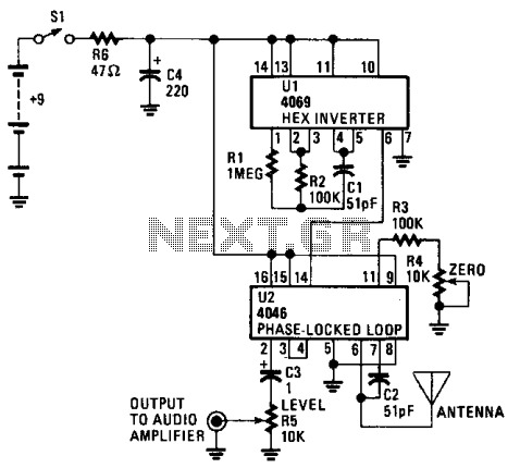
The CD4069 or 74C04 hex inverter is utilized as a fixed-frequency oscillator centered around 100 kHz. U2 includes the variable frequency oscillator and balanced modulator. The CD4046 functions as a phase-locked loop, with R3, R4, and C2 determining the...
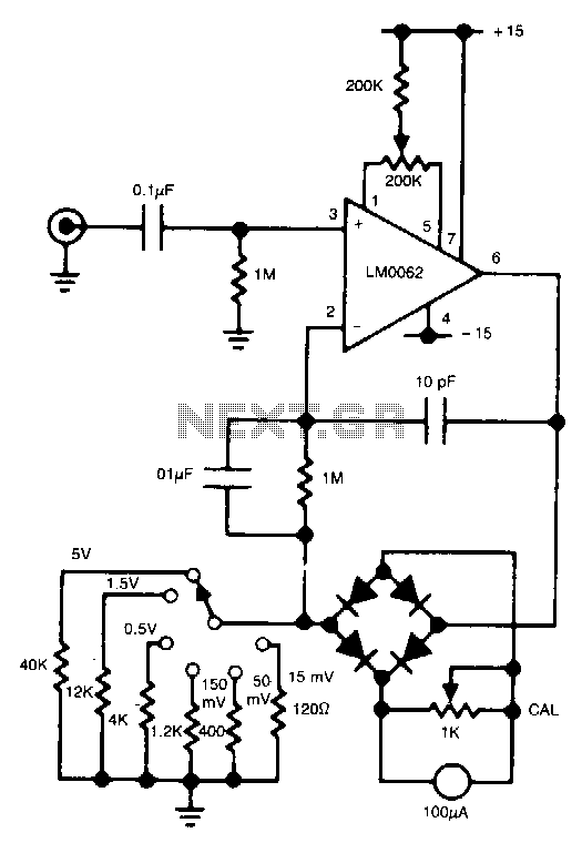
In this circuit, a diode bridge is utilized as a meter rectifier. The offset voltage is compensated for by the operational amplifier, as the bridge is part of the feedback network. The circuit employs a diode bridge rectifier, which consists...
This circuit is designed to digitally adjust the volume of an analog audio signal. It employs a single AVR microcontroller to generate a pulse width modulated (PWM) signal for control. The innovation of the circuit lies in the utilization...
The input mentions the 89S51/52 microcontrollers, but the accompanying image shows the 89C51. Clarification is needed regarding which microcontroller should be used with the provided .hex file without requiring changes to the file. The 89S51 and 89S52 are part of...
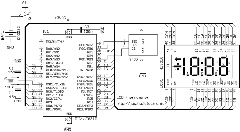
The circuit drives the LCD pins with 50% square waves. Each segment on this LCD is connected to the COM backplane and a separate pin. When a pin is driven in phase with the COM pin, the corresponding LCD...
This circuit generates a readout for a digital tachometer. IC9 functions as a 3-digit LED display driver, counter, and latch. IC8 operates the common cathode LEDs, which are activated by transistors Q1, Q2, and Q3. Refer to page 268,...