
Digital LCD thermometer ( PIC16F871 )
")
When the digits in all positions are updated, the "convert_segments" subroutine will map all the segments into the output pins of the PIC. For example, segment A of the first digit, called 1A is mapped to the RD6 pin of the PIC.
part number description
IC1 PIC16F871 Microchip microcontroller
IC2 TC77 Microchip digital temperature sensor
LCD1 7-segment 3-digit LCD
Q1 4MHz crystal
C1, C2 15pF ceramic capacitor
C3 100nF/6V ceramic capacitor
S1 ON/OFF switch
BAT1 CR2032 socket and Lithium battery
misc Printed Circuit Board (PCB), strip board or bread-board
housing for the electronics
The described circuit operates a 3-digit 7-segment LCD display using a PIC16F871 microcontroller. The LCD segments are controlled by generating 50% duty cycle square waves, allowing for efficient multiplexing of the display. Each segment is connected to a common backplane (COM) and individual pins, enabling the display of numerical values based on the temperature readings from the TC77 temperature sensor.
The interrupt routine is critical for inverting the states of the LCD pins, which alternates the segments' display states to create the illusion of continuous illumination. The segments' states are maintained in a 5-byte buffer in RAM, named `segments_buffer`, which stores the on/off states for each segment.
Temperature readings are obtained through the `tc77_ioread` function, with the results processed to convert the temperature value into a decimal representation. This value is then mapped to the corresponding segments of the LCD using a predefined mapping table, `segtable`, which specifies the bit patterns required to illuminate the correct segments for each digit. For instance, the digit '0' corresponds to the bit pattern "00111111", which activates segments A through F.
To enhance the display's accuracy, the last digit can represent fractional values, which are rounded and mapped using the `lookup_frac` table. This allows for the display of temperature values with decimal precision.
The `convert_segments` subroutine is responsible for translating the segment states into the output pins of the PIC microcontroller, ensuring that each segment of the LCD is driven by the appropriate pin. For example, the pin RD6 is designated for segment A of the first digit.
The circuit is powered by a CR2032 lithium battery, providing a compact and portable power source. The components are assembled on a printed circuit board (PCB), strip board, or breadboard, with an ON/OFF switch (S1) for power control. The design includes a 4MHz crystal (Q1) for clock generation, along with ceramic capacitors (C1, C2, C3) for stability and filtering.The circuit drives the LCD pins with 50% square waves. Each segment on this LCD is connected to the COM backplane and a separate pin. When a pin is driven in phase with the COM pin, the corresponding LCD segment gets zero voltage, and is off. When a pin is driven in reverse of the COM pin, the corresponding segment gets an alternating voltage, and lights up.
The interrupt routine is called periodically to invert all pins of the LCD to generate the 50% square wave. The pin states are stored in the RAM labeled segments_buffer, 5 bytes long. The interrupt also reads the temperature sensor for the actual values. The main program gets the temperature value from tc77_ioread, and calculates the temperature in celsius.
All digits of this decimal value are then converted into the values of the 7 segment of the LCD digits. This mapping table is located at the label segtable. For example, the digit 0 turn on the following digits: F, E, D, C, B, A because it sets bits as "00111111".
The 16 possible fraction values at the last digit are rounded and mapped to the last digit at the "lookup_frac" table. When the digits in all positions are updated, the "convert_segments" subroutine will map all the segments into the output pins of the PIC.
For example, segment A of the first digit, called 1A is mapped to the RD6 pin of the PIC. part number description IC1 PIC16F871 Microchip microcontroller IC2 TC77 Microchip digital temperature sensor LCD1 7-segment 3? digit LCD Q1 4MHz crystal C1, C2 15pF ceramic capacitor C3 100nF/6V ceramic capacitor S1 ON/OFF switch BAT1 CR2032 socket and Lithium battery misc Printed Circuit Board (PCB), strip board or bread-board housing for the electronics
🔗 External reference
Related Circuits
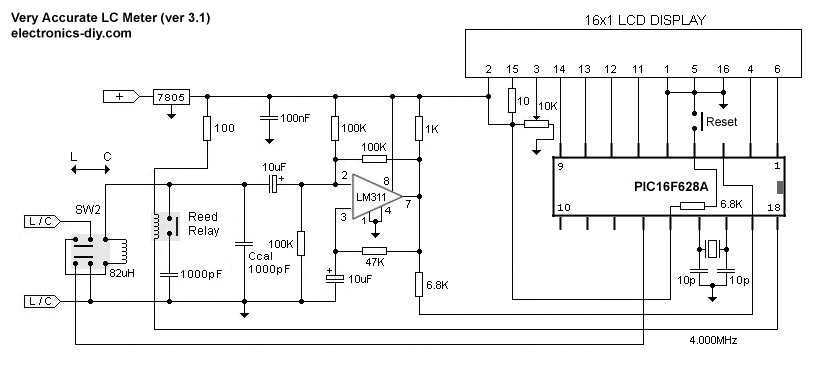
This is one of the most accurate and simplest LC inductance / capacitance Meters that one can find, yet one that you can easily build yourself. This LC Meter allows to measure incredibly small inductances starting from 10nH to...
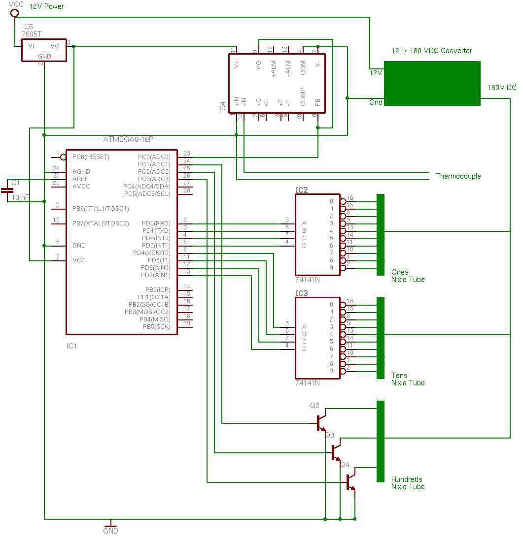
the entire circuit is comprised of integrated circuits. This makes for some easy organization when it goes to the circuit board for soldering. In addition, I used only 3 of the pins on the 3rd nixie tube for the...
The digital lock utilizes four common logic integrated circuits (ICs) to manage a relay activation by inputting a four-digit code via a keypad. The initial four outputs from the CD4017 decade counter (pins 3, 2, 4, and 7) are...
This circuit is a small +5V power supply, which is useful when experimenting with digital electronics. Small inexpensive wall transformers with variable output voltage are available from any electronics shop and supermarket. Those transformers are easily available, but usually...
This is a simple temperature measurement probe circuit. This circuit measures temperature either on a PC board or at the probe tip. The temperature measurement probe circuit is designed to accurately monitor temperature variations in various environments, including printed circuit...
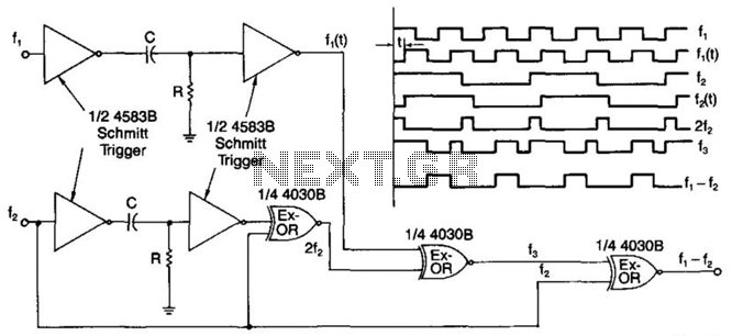
A simple digital mixer uses two dual-Schmitt triggers (4583B) and three exclusive-OR gates, incorporating an RC time-delay circuit to allow for easy adjustment of the output signal pulse width. The exclusive-OR gates can also function independently as a symmetrical...