
Single Supply Summing Amplifier for Audio Mixer

The inverting summing circuit serves as a fundamental building block in audio mixing applications, allowing multiple audio signals to be combined into a single output. This circuit typically employs operational amplifiers (op-amps) configured in an inverting mode. The inputs to the op-amp are connected through resistors, which determine the weighting of each input signal in the final mix.
In a typical setup, the op-amp is powered by dual supply voltages, which provide a greater dynamic range than a single-supply configuration. This dual supply allows the op-amp to handle both positive and negative signal excursions, thereby accommodating the full waveform of audio signals without distortion. The resistors connected to the inputs not only serve to scale the input signals but also ensure that the input impedance of the circuit remains high, minimizing loading effects on the preceding stages of the audio chain.
The feedback resistor connected from the output of the op-amp back to its inverting input sets the gain of the circuit. By adjusting the values of the input and feedback resistors, the designer can control the overall gain and mixing characteristics of the circuit. Additionally, the circuit can be designed to include features such as level adjustment and pan control, further enhancing its functionality in a mixer.
In summary, the inverting summing circuit is a crucial element in audio mixers, facilitating the combination of multiple audio sources while maximizing dynamic range and minimizing distortion through careful design and component selection.The basis of an audio mixer is an inverting summing circuit below. For real audio mixers, a single-supply voltage is seldom used. To increase dynamic range,.. 🔗 External reference
Related Circuits
The U2745B is a Phase-Locked Loop (PLL) transmitter integrated circuit (IC) designed specifically for low-cost radio frequency (RF) data transmission systems, supporting data rates up to 20 kBaud. It operates within a transmitting frequency range of 310 MHz to...
This is a circuit that generates white noise, rolled-off to drive earphones or a small speaker. White noise creates is a "rushing" sound, which sounds something like air rushing by your ear(s). White noise would be flat with frequency,...
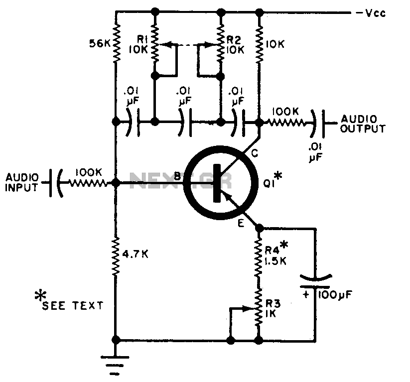
The circuit can be selectively tuned to two closely related tones. The selective frequency is determined by the values of the feedback circuit connected to the collector and base of Q1, which includes capacitors and resistors. When the specified...
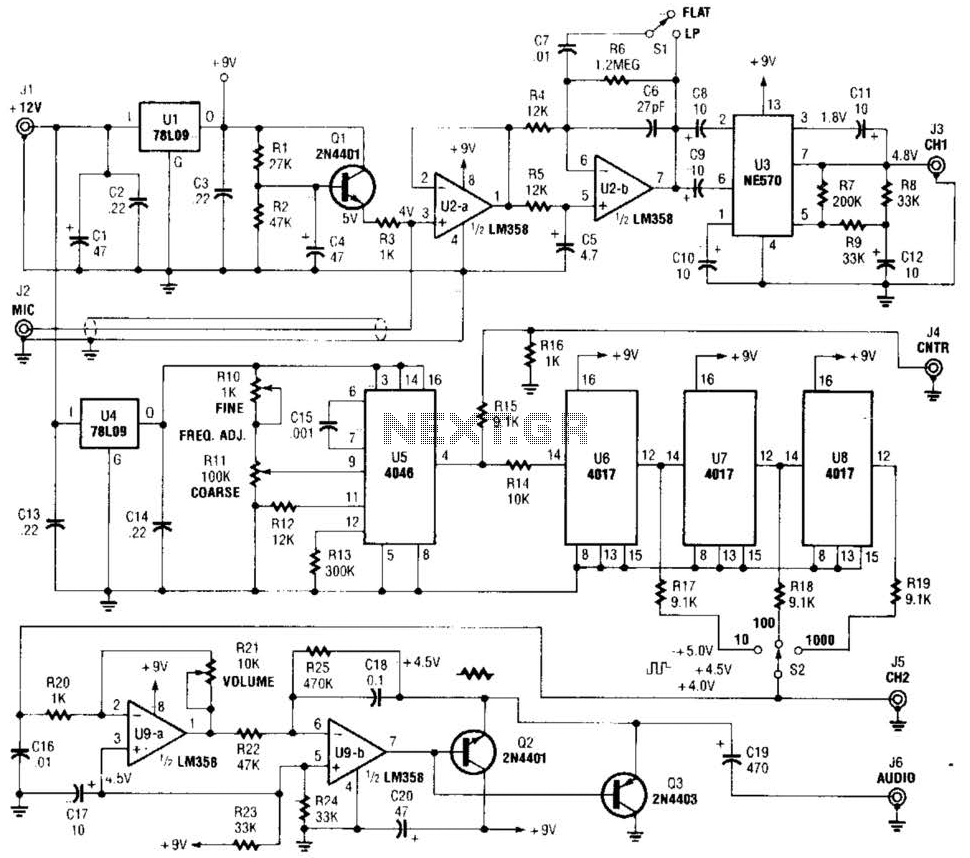
The precision audio frequency generator consists of several sub-circuits: an audio amplifier/filter circuit, an automatic level control, a variable voltage-controlled oscillator, a frequency divider circuit, an integrator, and an audio output amplifier. An electret microphone element is utilized to...
The target of this project was the design of a small portable mixer supplied by a 9V PP3 battery, keeping high quality performance. The mixer is formed assembling three main modules that can be varied in number and/or disposition...
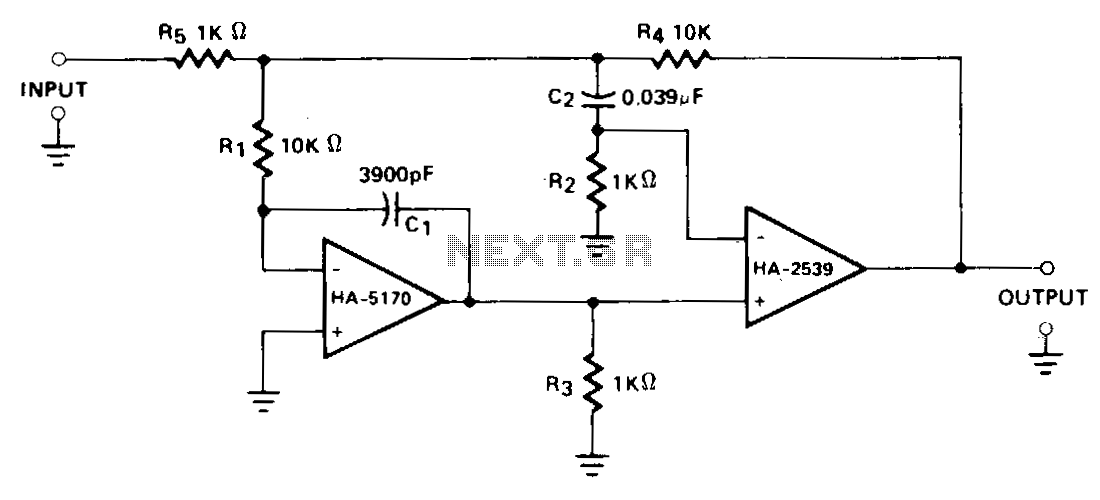
A composite configuration significantly reduces errors without compromising the high-speed, wideband characteristics of the HA-2539. The HA-2540 can also be utilized, although it exhibits slightly lower speeds and bandwidth response. The HA-2539 amplifies signals above 40 kHz, which are...