
Precision Audio-Frequency Generator Circuit

From there, the selected signal frequency is split into two paths; one path leads to CH2 (which connects to the oscilloscope's sweep synchronization input) and to an integrator that transforms the square-wave output of the divider into a triangular waveform. The output from the integrator is subsequently amplified and delivered to a set of stereo headphones via an audio output jack. One segment of the precision audio frequency generator employs an electret microphone element to capture audio from a piano. This signal is processed and sent to one channel of a dual-trace oscilloscope. The other segment of the circuit generates a variable-frequency signal that is directed to a digital frequency counter and, after conditioning, is presented to the second channel of the oscilloscope and output to a set of stereo headphones.
The precision audio frequency generator is designed to provide accurate and versatile audio signal generation and analysis. The audio amplifier/filter circuit serves to enhance the captured audio signal from the electret microphone while filtering out unwanted noise, ensuring that the output is clean and suitable for further processing. The automatic level control adjusts the gain of the audio signal dynamically, allowing for consistent output levels regardless of variations in the input signal amplitude.
The variable voltage-controlled oscillator is a critical component that allows for a wide range of frequency generation. This VCO can be finely tuned to produce specific audio frequencies, which is essential for applications in audio testing and synthesis. The digital frequency counter provides real-time frequency readouts, facilitating precise measurements and adjustments during operation.
The frequency divider circuit is equipped with a selector switch that enables the user to choose the division factor, thereby allowing for flexibility in frequency output. This feature is particularly useful when synchronizing signals with external equipment or when specific frequency ranges are required for testing.
The integrator plays a vital role in converting the square wave output from the frequency divider into a triangular waveform, which is often more suitable for audio applications and provides a smoother sound output when amplified. The output from the integrator is then amplified further to ensure adequate signal strength before being delivered to the headphones.
Overall, the precision audio frequency generator is a sophisticated device that integrates various electronic components to facilitate comprehensive audio signal generation, analysis, and output, making it an invaluable tool for audio engineers and technicians in various applications. The precision audio-frequency-generator consists of several sub circuitsan audio-amplifier/filter circuit, an automatic level control, a variable voltage-controlled oscillator, a frequency divider circuit, an integrator, and an audio output amplifier. An electret microphone element is used to pick up the audio tone produced by the instrument. That signal is then fed to an amplifier/filter/level-controlled circuit and output via channel 1 (CHI) to an oscilloscope for display.
The variable voltage-controlled oscillator (VCO) is used to produce a signal of from less than 10 kHz to more than 99 kHz. The VCO output is fed to a digital frequency counter for display, and is also routed to a chain of frequency dividers, where the signal is divided by 10, 100, or 1,000, depending on the setting of a selector switch.
From there, the selected signal frequency divides along two paths; one going to CH2 (which feeds the oscilloscope`s sweep synchronization input) and to an integrator that converts the square-wave output of the divider into a triangular waveform. The output of the integrator is then amplified and fed to a set of stereo headphones via an audio output jack.
One section of the precision audio-frequency generator uses an electret microphone element to pick up audio from the piano. That signal is then processed and sent to one channel of a dual-trace oscilloscope. The other section of the circuit is used to produce a variable-frequency signal that is fed to a digital frequency counter and, after conditioning, is presented to the second channel of the scope and output to a set of stereo headphones.
Related Circuits
The ML4423 is an integrated controller designed for single-phase and two-phase AC induction motors. It features PWM (Pulse Width Modulation) capabilities for speed control and includes various protection circuits such as short circuit protection, fire protection, and a reference...
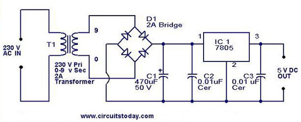
A 5V power supply using IC 7805 is designed and explained with a neat circuit diagram. The circuit for a 5V power supply utilizing the IC 7805 voltage regulator is a straightforward and efficient design that provides a stable output...
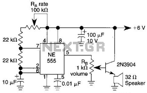
Ra sets the rate while RH sets the volume of clocks in the speaker. The 555 is configured as a low frequency oscillator. The circuit is powered by a 6 V battery. The circuit utilizes a 555 timer IC configured...
An ultrasonic sound wave can be generated using an electronic circuit. This simple electronic circuit can generate an ultrasonic wave with a frequency range of 12 kHz and above. The electronic circuit designed for generating ultrasonic sound waves typically utilizes...
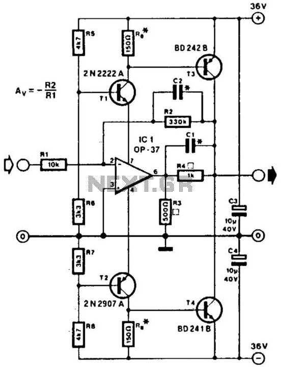
This line driver is capable of driving low-impedance lines with a maximum output of 70 V peak-to-peak. IC1 functions as a low-noise operational amplifier suitable for operation at 15 V. T1 and T2 serve as voltage regulators for the...
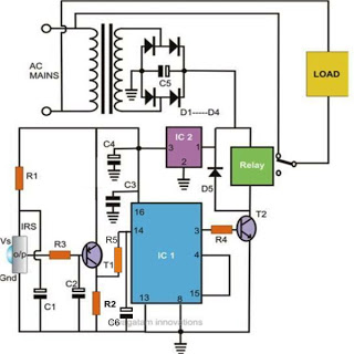
Controlling household electrical gadgets or any electrical equipment remotely can be enjoyable. While using a remote to control devices like a TV or DVD player is a common experience, managing other domestic appliances such as water pumps and lights...