
2 Transistors Mini MW Transmitter

The Mini MW Transmitter circuit is designed to operate in the medium wave band, typically around 530 to 1700 kHz. It employs two transistors, SA103 and SA101, which function as the core oscillating elements of the transmitter. The SA103 is often used for its high-frequency response and stability, while the SA101 serves as a complementary device to enhance the circuit's overall performance.
The circuit usually begins with the SA103 configured as a common emitter oscillator. The oscillator generates a radio frequency (RF) signal, which is then modulated by an audio input. The modulation can be achieved by varying the biasing conditions of the transistor, effectively superimposing the audio signal onto the RF carrier wave.
The output from the SA103 is fed into the SA101 transistor, which is configured as a buffer or amplifier. This transistor amplifies the RF signal, ensuring that it has sufficient power to drive the antenna. The antenna, typically a simple wire or whip antenna, radiates the modulated RF signal into the surrounding environment, allowing it to be received by standard AM radios.
Additional components in the circuit may include resistors, capacitors, and inductors, which are used to set the frequency of oscillation and filter unwanted harmonics. Proper tuning of these components is critical to achieving the desired frequency stability and signal quality.
Overall, the Mini MW Transmitter circuit is a straightforward yet effective design for transmitting audio signals over medium wave frequencies, making it suitable for various applications, including hobbyist projects and educational demonstrations in electronics.This is a Mini MW (Medium Wave) Transmitter circuit. This circuit consist of combination of transistors SA103 and SA101. Those transistors is used as oscillator. 🔗 External reference
Related Circuits

This mini logic analyzer is a tool that allows users to observe the logic transitions (0 or 1) of digital data signals on an LCD display. Digital data signals can be sourced from various electronic components, such as the...
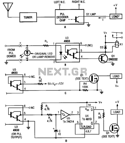
Several possible interface circuits are presented for use with a remote-control transmitter. The circuit labeled A demonstrates a typical FM stereo MUX decoder with a load connected directly to the open-collector output of a TA7343 PLL. The circuit labeled...

This FM transmitter circuit is very simple and has an acceptable transmission range. The signal transmitted from this FM transmitter circuit can be received at almost 300 meters in open air. The circuit requires a 3-volt operating voltage and...
Information about building a small radio transmitter, which has a PCB measuring 1.75" x 2.5" (45mm x 68mm) and has a range of approximately 30 yards. The documentation states that the frequency range is 100-108 MHz, but it has...

The circuit was constructed using a few components powered by a 9 V battery for sensing the presence of bugs transmitting within the frequency modulation range. Frequency Modulation (FM) transmits its signal or information over a carrier wave by...

The range of this FM transmitter is approximately 100 meters when powered by a 9V DC supply. The circuit consists of three main stages. The first stage is a microphone preamplifier utilizing a BC548 transistor. The second stage features...