
siren circuit

The electronic siren circuit operates using a basic configuration of two transistors, typically configured as an astable multivibrator. This arrangement allows the circuit to oscillate, creating a square wave signal that drives the connected speaker. The choice of an 8-ohm speaker is crucial, as it matches the output characteristics of the circuit, ensuring optimal sound production.
The circuit begins with a power supply of 9 volts, which is connected to the base of the first transistor through a resistor. This resistor limits the current flowing into the base, controlling the transistor's switching action. The first transistor, when activated, allows current to flow from the collector to the emitter, effectively turning on the second transistor. This second transistor, in turn, amplifies the current to drive the speaker.
Feedback from the speaker is typically routed back to the base of the first transistor through a capacitor, establishing a feedback loop that sustains oscillation. The frequency of oscillation can be adjusted by varying the values of the resistors and capacitors in the circuit, allowing customization of the siren sound.
Overall, the simplicity of this design makes it an effective solution for generating siren sounds in various applications, such as alarms, warning systems, or other audio signaling devices. Proper attention to component selection and circuit layout will ensure reliable operation and sound quality.This is a simple electronic siren circuit, which can be used in many circuits where the need of siren is required. The circuit is very simple using only two transistors and few other components and it will generate siren sound when power is applied.
Use 8 ohms speaker and apply 9 volts to the circuit. 🔗 External reference
Related Circuits

The following diagram is the clock generator circuit diagram built using NAND gate logic integrated circuits (ICs). The circuit can utilize either the IC 7400, which is a TTL type, or the IC 4011, which is a CMOS type....

This is a compact collection of amplifiers configured in a bridge connection. The output power is low, making them suitable for general applications. They can be utilized with small active loudspeakers, car stereos, and similar devices. The only limitation...

This circuit is effective for lamp and heater loads. Some circuits driving reactive loads require integral cycling and zero-voltage switching when an identical number of positive and negative half-cycles of voltage are applied to the load during a power...
A simple test circuit designed for troubleshooting audio and radio equipment. It can inject a square wave signal rich in harmonics or be used with headphones as an audio tracer. A single-pole double-throw switch is utilized to toggle between...

This circuit is a simple musical alarm that generates a tone when water or another conductive liquid touches the two sensor wires provided. It utilizes four transistors and a melody generator integrated circuit (IC) M3482. When water bridges the...
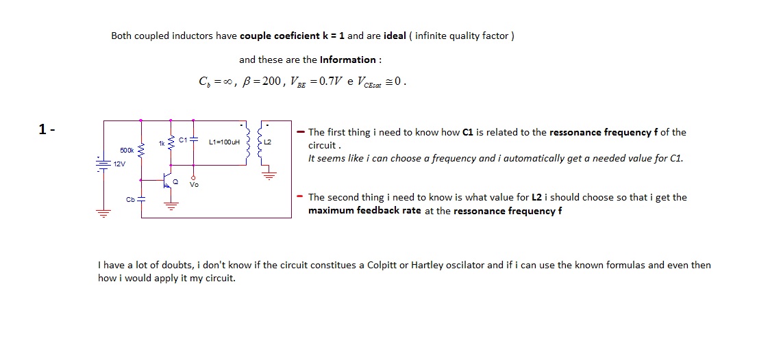
The first thing to understand is how capacitor C1 is related to the resonance frequency f of the circuit. It appears that selecting a frequency allows for the automatic determination of the necessary value for C1. There are uncertainties...