
siren circuit

The circuit operates on a simple principle of sound generation through frequency modulation, utilizing a capacitor and a switch. When switch S1 is pressed, it initiates the charging of capacitor C1, which in turn alters the frequency of the sound produced. The charging process of the capacitor is directly related to the increase in frequency, creating a rising pitch in the siren sound.
The frequency modulation can be achieved using a simple oscillator circuit, typically involving a 555 timer IC configured in astable mode. In this configuration, the frequency of oscillation is determined by the values of the resistor(s) and capacitor connected to the timer. As capacitor C1 charges through the resistor, the time constant of the RC network influences the frequency, resulting in a higher pitch sound.
Upon releasing switch S1, the capacitor C1 begins to discharge. The discharge process causes a decrease in the voltage across the capacitor, leading to a reduction in frequency and subsequently a drop in pitch of the siren sound. This creates a dynamic sound effect that mimics a traditional siren.
To ensure proper functioning, it is important to select appropriate values for the resistor and capacitor to achieve the desired frequency range. Additionally, the circuit may include a speaker or buzzer to convert the electrical signals into audible sound. Proper connections and component ratings must be verified to maintain circuit integrity and performance.
In summary, this circuit effectively utilizes the charging and discharging characteristics of capacitor C1 in conjunction with a switch to create a siren sound that varies in frequency, providing a simple yet effective sound modulation application.This circuit will generate siren sound when S1 pressed and increate sound frequency becuase capacitor C1 charged when switch S1 released the frequency will decreated(C1 discharged). 🔗 External reference
Related Circuits
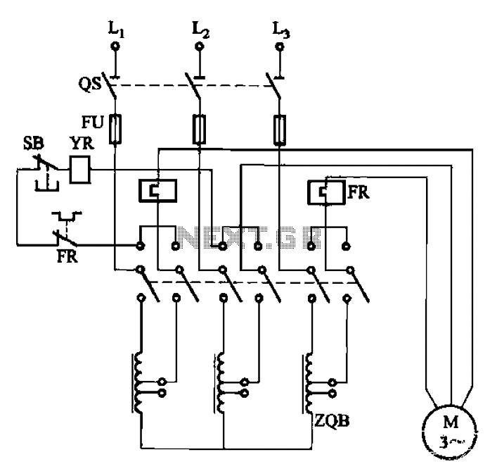
The circuit illustrated in Figure 3-47 involves a three-phase AC motor that is initially connected through a step-down autotransformer. To initiate operation, the power switch is closed, and the operating handle is pushed to the start position. Once the...

A, B, and C are used for a high-power split-phase system. The A + B' C' arrangement serves as a phase line for a range generator. The A-A' indole path string includes two 220V / 15W bulbs, which are...
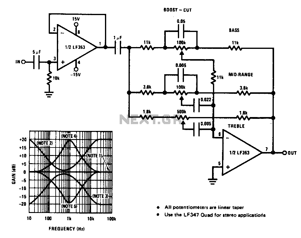
A simple single-transistor circuit provides an approximate 15 dB boost at 100 Hz and a 15 dB cut at 15 kHz. A low-noise audio transistor is utilized, and the output can be directly connected to any existing amplifier volume...

Many people might be excited by the sound of a siren, as it is often associated with emergency events such as accidents. However, one may wonder about the underlying mechanisms that produce this alerting sound. The siren sound commonly used...
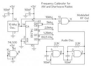
The following circuit illustrates an AM/Shortwave Radio Frequency Calibrator Circuit Diagram. This circuit is based on the 74LS93 IC. Features: The .. The AM/Shortwave Radio Frequency Calibrator Circuit utilizes the 74LS93 integrated circuit, which is a 4-bit binary counter. This...
This is a car alarm simulator that uses an LED as a simulation output. This simple circuit can indicate whether a car is running or not by detecting the voltage difference when the car is on or off. This...