
Automotive Circuits

The car alarm simulator circuit primarily consists of a voltage detection mechanism that monitors the electrical state of the vehicle. The circuit is designed around a voltage comparator, which is typically implemented using an operational amplifier (op-amp). The op-amp compares the voltage level from the vehicle's battery with a predefined reference voltage.
When the vehicle is turned on, the voltage at the op-amp's input exceeds the reference voltage, resulting in a high output signal. This output can be connected to an LED, which will illuminate to indicate that the car is running. Conversely, when the car is turned off, the voltage drops below the reference level, causing the op-amp output to go low, which turns off the LED.
Additional components that may be included in the circuit are resistors to set the reference voltage and capacitors for noise filtering. A potentiometer can also be integrated to allow for adjustable sensitivity of the voltage detection. The circuit may be powered by the vehicle's battery, ensuring it operates reliably under the conditions present in an automotive environment.
This car alarm simulator circuit serves as a useful tool for testing and demonstrating the functionality of car alarm systems, providing a visual indication of the vehicle's operational status in a straightforward and effective manner.This is a car alarm simulator which using the LED as a simulation output. This simple circuit can tell you whether your car is running or not by detecting the voltage difference when the car is on and off. This occurs because when your car. 🔗 External reference
Related Circuits
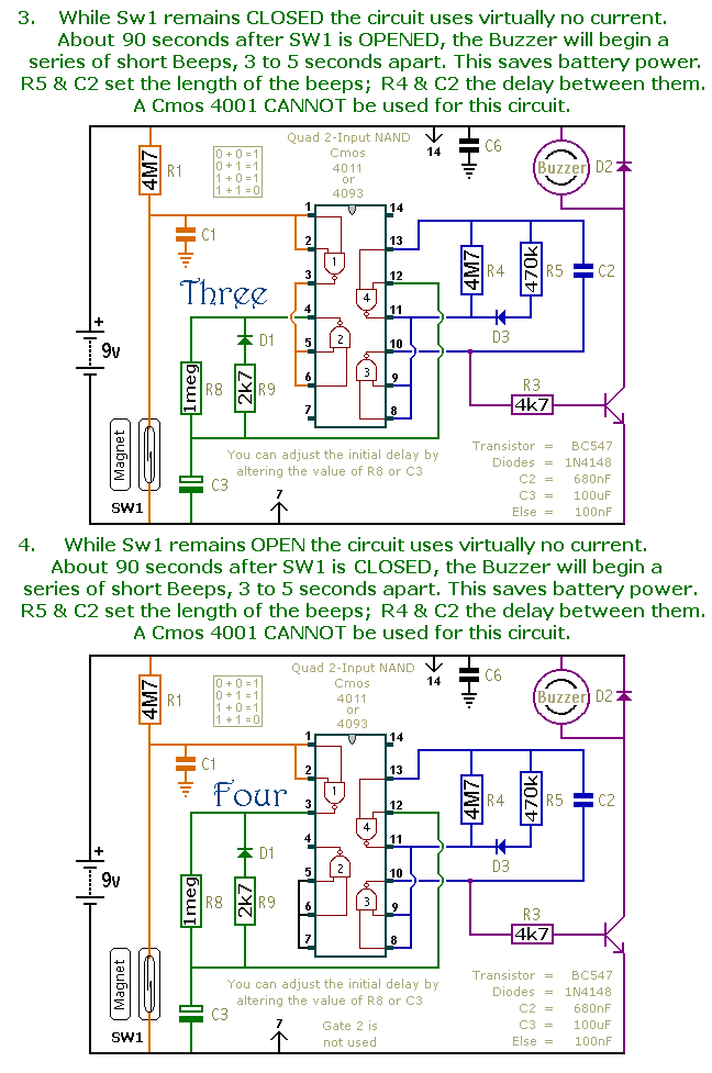
This is a collection of compact, self-sufficient alarm circuits designed for low standby current, making them ideal for battery operation. Some circuits are activated by normally-open and normally-closed switches, while others respond to variations in light or temperature. This...
The use of a quarter-wave parallel-wire line as a tuning unit has been discussed in the chapter on Short-Lines, where it was pointed out that these circuits have comparatively high Q even at higher frequencies. Their significant length (approximately...
Crystal oscillator integrated circuits, specifically two diagrams of oscillator circuits with oscillation frequencies of 10 MHz and 20 MHz. Crystal oscillators are essential components in various electronic applications, providing stable frequency references for timing and synchronization purposes. The circuits presented...

These circuits could be used as the basis for Model Railroad DCC Boosters or PWM motor controllers. The first schematic is for a basic 3 Amp - DCC Booster using the LMD 18200 CMOS, H-Bridge. Included in the design...
Typically, when a car door is closed, the dome light turns off immediately. This circuit allows the dome light to gradually fade in brightness before eventually turning off. An electronic transformer dims halogen lamps and is a straightforward device...
This is a simple mains power failure alarm circuit that activates an alarm when the mains supply is lost. Unlike many similar circuits, this design does not require a backup power source, such as a battery, to operate the...