
Siren Police Tone Circuit

The police tone siren circuit typically utilizes a 555 timer IC configured in astable mode to generate a square wave output, which simulates the sound of a police siren. The frequency and duty cycle of the output signal can be adjusted using variable resistors VR1 and VR2.
In this circuit, the 555 timer is powered by a suitable DC voltage source, often ranging from 5V to 15V, depending on the specific requirements of the siren. The output from the timer is connected to a power amplifier stage, which drives a loudspeaker or siren unit, producing the audible sound.
The timing components, including resistors and capacitors, are selected to set the desired frequency of the siren tone. The use of variable resistors allows for fine-tuning of the sound, enabling the user to achieve the characteristic rising and falling pitch associated with police sirens.
Proper layout and grounding techniques should be employed in the circuit design to minimize noise and ensure reliable operation. Additionally, protection components such as diodes may be included to safeguard the circuit from voltage spikes generated by the inductive load of the speaker.
Overall, this circuit serves as an effective solution for simulating a police siren tone, suitable for various applications in alarm systems or educational projects.Here is police tone circuit of siren. this simple and very easy to make it. vr 1 and vr 2 for change delay sound of siren. simple and easy. if sound output not. 🔗 External reference
Related Circuits
Generating long delays of several hours can be achieved using a low-frequency oscillator and a binary counter. A single Schmitt Trigger inverter stage (1/6 of 74HC14) functions as a square wave oscillator, producing a low frequency of approximately 0.5...

The CD 4047 is a low-power monostable and astable multivibrator that requires only an external capacitor and a resistor to produce output pulses. The CD 4047 integrated circuit (IC) is designed for generating precise timing pulses and can operate...
A capacitance meter is an essential instrument for electronics hobbyists and professional electronic technicians. A capacitance meter is a specialized device designed to measure the capacitance of capacitors in various electronic circuits. It typically features a digital or analog display...
A resistor divider is used to attenuate a signal in a manner that is suitable for situations requiring a higher signal amplitude. A resistor divider is a fundamental circuit configuration that utilizes two resistors to create a voltage output that...
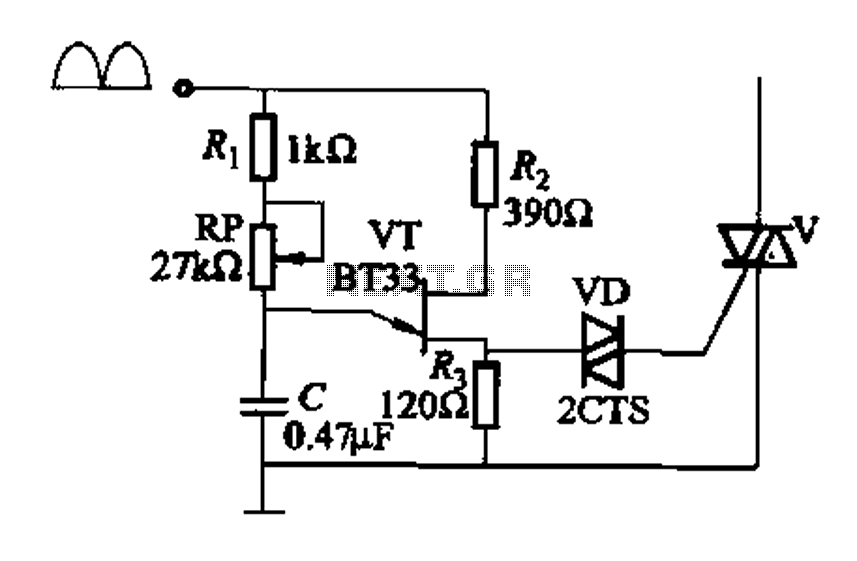
Figure 16-29 (a) illustrates the trigger output through a resistor R2, while Figure 16-29 (b) depicts the integration of a programmable unidirectional transistor (PUT) trigger circuit. The adjustable potentiometer RP can modify the conduction angle of the TRIAC to...

This design circuit is a tachometer circuit based on the LM2907 integrated circuit, which can provide zero-crossing data to a digital system. At each zero crossing of the input signal, the charge pump alters the state of capacitor C1...