
Six LED Stereo VU Display

The circuit diagram also includes a simple battery level indicator. In mobile phones, battery levels are typically displayed in dot or bar style, allowing users to easily recognize the battery status. Additionally, this document presents a design diagram for an electronic quiz game buzzer circuit, which allows up to eight participants, each assigned a switch (button) to signal their readiness to answer questions. Furthermore, a simple adjustable analog timer circuit is described, which can be used for various applications such as setting time limits during games or as an egg-timer in the kitchen. The timer circuit activates when switched on, indicated by a green LED.
Moreover, a water-level indicator circuit is detailed, which utilizes a 7-segment display to show the water level (low, half, and full) in a tank. A buzzer is included to alert users of potential overflow. The display indicates levels with the letters L, H, and F for low, half, and full, respectively.
Lastly, a stereo VU booster circuit diagram based on the transistor FCS9014 is provided, which is typically used for pre-amplification and regulation. This circuit should be connected to the audio channel before the amplifier module. When using a tone control or equalizer module, it is advisable to connect this circuit to the wiring before the tone control or equalizer. Additionally, there is a circuit designed to monitor the power capacity of a 12V Lead-Acid battery, with battery power levels indicated by LEDs. This straightforward circuit allows for monitoring the charging process effectively, with final adjustments being simple and requiring only a digital voltmeter for calibration.The following circuit is six LED stereo VU display diagram which build using Dot/Bar Display Driver IC LM3915. This VU disply should be connected before amplifier module circuit. You may connect this circuit at pre-amp output, tone control input/output or equaliser input/output. The LM3915 is a monolithic integrated circuit that senses analog volt age levels and drives ten LEDs, LCDs or vacuum fluorescent displays, providing a logarithmic 3 dB/step analog display. One pin changes the display from a bar graph to a moving dot display. LED current drive is regulated and programmable, eliminating the need for current limiting resistors.
The LM3915 ²s 3 dB/step display is suited for signals with wide dynamic range, such as audio level, power, light intensity or vibration. Audio applications include average or peak level indicators, power meters and RF signal strength meters.
Replacing conventional meters with an LED bar graph results in a faster responding, more rugged display with high visibility that retains the ease of interpretation of an analog display. Here the circuit diagram of simple and easy made battery level indicator. In general, in mobile phones, the battery levels is displayed in dot or bar style. This helps you to effortlessly acknowledge the battery level. On this page we provide a circuit that helps you to recognize the battery level of a instrument from.
This is the design diagram of electronic jam. This jam circuit can be implemented in quiz contests in which any participator who pushes his switch (button) prior to the other participants, will get the first opportunity to answer a question. The circuit provided right here allows up to eight participants with each one assigned a. This is a very simple adjustable analog timer circuit diagram. You can build this circuit just for fun, for newbie project or may be. , this circuit could be used to set a time limit when playing games or as an egg-timer in the kitchen.
The circuit will start timing when switched on. The green LED. Here the water-level indicator which use a 7-segment display, to show the water level (low, half and full) in the tank. Moreover, a buzzer is utilized to warn you of water overflowing from the tank. The circuit shows the water level by displaying L, H and F for low, half and full, respectively. The circuit. This is a stereo VU booster circuit diagram based on transistor FCS9014 which usually used for pre-amp and regulator circuit.
This circuit should be connected to audio channel before amplifier module. If you are using tone control or equaliser module, it`s better to connect this circuit to the wire connection before tone control / equaliser. . This circuit is designed to monitor the level of power capacity at 12V Lead-Acid battery. Battery power level will be indicated by LEDs. This easy circuit makes it possible to monitor the charging process to a higher level. Final adjustsments are simple and easy and the only device required is a digital voltmeter for the. 🔗 External reference
Related Circuits
An LMX1601 Phase locked loop, a discreet FET VCO, and an AVR microcontroller combine to make a stable, easy to use monophonic FM transmitter that includes an audio activated switch that turns the transmitter on only when it is...
This circuit was designed as a warning flasher to alert road users to dangerous situations in the dark. Alternatively, it can act as a bicycle light. The circuit operates by utilizing a light-emitting diode (LED) as the primary visual alerting...

This is a circuit using the LM3914 LED VU meter. It utilizes the LM3914 integrated circuit (IC1) along with a BC109C transistor. The circuit displays the level of audio signals (power music) in decibels (dB) across six levels using...
The clock circuit above uses seven ICs and 19 LEDs to indicate binary coded decimal time. The LEDs can be arranged so that each horizontal group of 3 or 4 LEDs represents a decimal digit between 0 and 9...
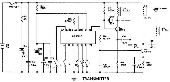
This circuit resembles that of a car radio-controlled toy with seven control functions: forward, forward-left, forward-right, backward, backward-left, backward-right, and stop. Additionally, this radio frequency circuit can be utilized for other electronic circuits that require a simple wireless motor...
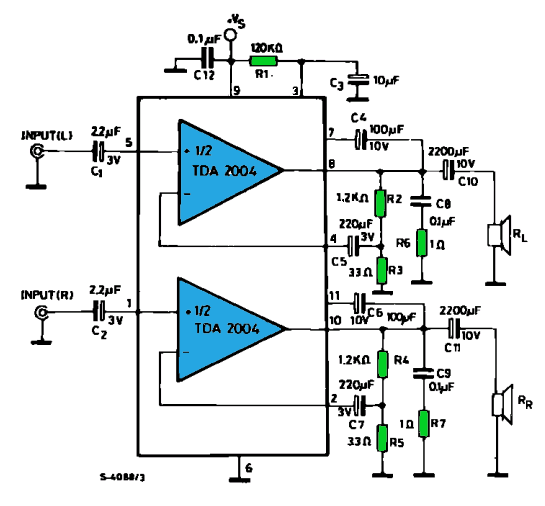
The TDA2004 integrated circuit (IC) is a popular choice among audio electronics enthusiasts due to its affordability and availability. This IC is often utilized in audio amplifier designs because it features two outputs and inputs, making it easy to...