
AVR Microcontrolled PLL FM Transmitter

In order to function, the LM1601's registers need to be loaded. In particular, they need to be loaded with the divide ratios for the reference and signal (VCO in this case) counters, and to set some control parameters. To load the registers, an Atmel AT90S2313 is employed. It could have been any microcontroller with 3 I/O pins, but the AVR processor was chosen, utilizing leftover AT90S2313 chips from another project. The ATtiny2313 can be substituted without changing the source code. The 20 pin DIP appears significantly larger compared to the diminutive LMX1601, reflecting the technological advancements over the decades between the introduction of these two packages.
The LMX1601 has a reference divider, which divides the 4 MHz clock from the microcontroller's crystal oscillator down to a 12.5 kHz reference frequency. The feedback divider, referred to as "16 Bit AUX N Counter" in the data sheet, is preceded by a divide-by-8 prescaler. These factors determine the channel spacing for the phase locked loop, with a resulting spacing of 8 x 12.5 kHz = 100 kHz. The AUX N register contains the divide ratio for the feedback divider, and the phase locked loop attempts to configure the VCO to operate at a frequency equal to the value written to the AUX N register, multiplied by 100 kHz. The actual frequency of oscillation depends on the range of the VCO itself, allowing the center frequency of the resulting frequency-modulated oscillator to be set with 100 kHz resolution, enabling it to be positioned on or between allocated FM broadcast channels throughout most of the world.
If a value of 1000 is written into the AUX N register, the PLL will attempt to run at 100 kHz x 1000 = 100 MHz. The firmware utilizes an 8-bit count as the "channel" number, with the highest frequency occurring when the channel number is 255, set to 108 MHz by adding an offset of 825 to the channel number. This offset is implemented to avoid interference with aviation communications, which occupy the spectrum just above the FM broadcast band. When the frequency increment and decrement buttons are pressed, the channel number adjusts accordingly. The routines limit the channel number to those frequencies between 88.0 MHz and 108.0 MHz.
After changing the channel number, the microcontroller waits for 30 seconds before writing the channel number to EEPROM. This precaution prevents excessive write cycles to the EEPROM, which has a limited number of write cycles. Transitioning from 100 MHz to 108 MHz requires 180 button presses, a manageable task given that it would typically only need to be performed a few times during the transmitter's lifespan.
The actual frequency of the oscillator is contingent on the microcontroller crystal oscillator. In practical applications, such as with radios featuring digital tuning, accurate frequency alignment is critical. This requirement was addressed by selecting a 4 MHz crystal and adding a small capacitor in series to fine-tune the frequency down by a few parts per million.
The selected oscillator for the VCO is the same used in the Band Switched Test Oscillator project, known for its ability to tune across the entire FM band even with a 3-volt tuning voltage. Its performance has been validated through listening tests on an FM radio during development.An LMX1601 Phase locked loop, a discreet FET VCO, and an AVR micro controller combine to make a stable, easy to use monophonic FM transmitter that includes a an audio activated switch that turns the transmitter on only when its being used. The common characteristic of all of the previous low power FM transmitters I've built over the decades, is that their operating frequency is determined by an LC resonant circuit.
Some of them had excellent stability, some of them didn't, but I had always wanted to make one that is crystal controlled. Various schemes had been considered from time-to-time, including the direct approach of modulating the load capacitance of a a crystal oscillator, a whimsical phase modulation scheme involving a phase shifter, some balanced modulators, and limiting amplifiers, and at times, the down-to-earth and sober approach of modulating a VCO within a phase locked loop (PLL). While browsing Digikey's online catalog, I found the LMX1601 frequency synthesizer chip and thought: "Just maybe, the PLL approach is finally within my grasp." The LMX1601, which apparently was designed for use in cell phones, includes everything need to make two phase locked loops except for the VCOs.
More importantly, one of the PLLs, specifically the "AUX" PLL, is specified to work in the FM broadcast band. The LMX1600 and the LMX1602 were also considered, but the LMX1601 was selected because it has a "500 MHz option", meaning that it can work down to about 50 MHz.
The Phase Locked Loop In order to function, the LM1601's registers need to be loaded. In particular, they need to be loaded with the divide ratios for the reference and signal (VCO in this case) counters, and to set some control parameters. To load the registers, I used a Atmel AT90S2313. It could have been any microcontroller with 3 I/O pins, but I had chosen the AVR processor, and I still have a lot of AT90S2313 chips left over from another project.
To the best of my knowledge, the ATtiny2313 can be substituted without changing the source code. The 20 pin DIP appears monstrously large compared to the diminutive LMX1601. The size difference is an indication of the passing of the three of four decades that elapsed between the introduction of these two packages. The LMX1601 has a reference divider, which I used to divide the 4 MHz clock from the micro controller's crystal oscillator, down to 12.5 kHz reference frequency.
The feedback divider, referred to as "16 Bit AUX N Counter" in the data sheet, is proceeded by a divide by 8 prescaler. These factors determine the channel spacing for the phase locked loop. 8 X 12.5 kHz = 100 kHz. The AUX N register contains the divide ratio for the feedback divider, and the phase locked loop tries to make the VCO operate at a frequency equal to the value written to the AXU N register, times 100 kHz.
I say "tries" because the actual frequency of oscillation depends on the range of the VCO itself. This means that the center requency of the resulting frequency modulated oscillator can be set with 100 kHz resolution, enabling it to be set either on or between allocated FM broadcast channels throughout most of the world. If a value of 1000 is written into the AUX N register, the PLL will try to run at 100 KHz X 1000 = 100 MHz.
The math isn't so hard, and I skipped the hard math -the loop gain and bandwidth calculations- so this should be an easy project, mathwise. In the firmware, an 8 bit count is used as the "channel" number. The highest frequency, which occurs when the channel number is 255, is set to 108 MHz by adding an offset of 825 to the channel number.
I did this because the part of the spectrum just above the FM broadcast band is used for aviation communications in most, if not all, parts of the world. When the frequency increment and decrement buttons are pressed, the channel number increments or decrements, respectively.
The button increment and decrement routines that limit the channel number to those that correspond to frequencies between 88.0 Mhz and 108.0 MHz. After the channel number is changed, the microcontroller waits for 30 seconds before writing the channel number to EEPROM.
EEPROMs are only capable of a limited number of cycles, and the 30 second timer prevents the EEPROM from being written to each time a button is pressed. Going from 100 MHz to 108 MHz requires pressing the increment button 180 times. That's not really that much work, considering that it would normally only have to be done a few times in the life of the transmitter.
The actual frequency of the oscillator depends on the microcontroller crystal oscillator. I am using this with a couple of radios with digital tuning, and one of them has a pretty narrow detector, so for low distortion, I needed to have the transmitter very close to the frequency the receiver expects it to be. In other words, the transmitter, and therefore the microcontroller crystal oscillator had to be accurate.
I solved the problem in my case by selecting a 4 MHz crystal this is close, and then adding a small capacitor in series with it to drop the frequency by a few more parts per million. The VFO The oscillator I chose for the VCO is the same one used in the Band Switched Test Oscillator project because I know from experience, that it can tune through the entire FM band, even with a 3 volt tuning voltage, and also because it is quiet enough to use for this sort of thing.
I had listened to the basic oscillator plenty on an FM radio while working on the Band Switched Oscillator project. 🔗 External reference
Related Circuits
L2 RFC (resistance 1MΩ with an inductor wrapped around it consisting of several coils made from fine insulated wire. The inductor is connected in parallel with the resistance, forming a parallel L-R circuit.) With capacitors C7 and C8, the...
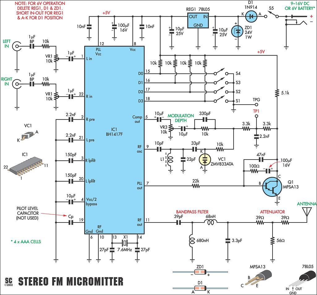
This new stereo FM Micromitter is capable of broadcasting good quality signals over a range of about 20 meters. It is ideal for broadcasting music from a CD player or any other source so that it can be picked...
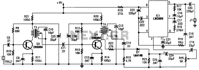
The 2.25-MHz oscillator Q1 drives amplifier Q2 and XTAL1, an ultrasonic transducer. The transducer is a lead zirconate-titanate type. Taps on T1 and T2 provide low-impedance drive points. The circuit consists of a 2.25-MHz oscillator (Q1) that serves as the...
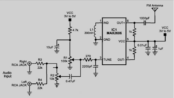
The MAX2605 and MAX2609 are compact, high-performance intermediate frequency (IF) voltage-controlled oscillators (VCOs) specifically designed for demanding portable wireless communication systems. They feature a monolithic construction with low noise and low operating power consumption, housed in a small 6-pin...
Many applications require a large number of keys connected to a computing system. Examples include PC keyboards, cell phone keypads, and calculators. Connecting a single key to a microcontroller unit (MCU) is straightforward; however, connecting 10 or 100 keys...
Long-distance infrared transmitter circuit diagram. This simple circuit offers a considerable range by utilizing three infrared transmitting LEDs (IR1 through IR3) in series to enhance the radiated power. To further improve directivity and power density, the IR LEDs can...