
Six thyristor overcurrent protection circuits

Capacitor C3 plays a crucial role in timing applications within electronic circuits. Its primary function is to manage the delay time by controlling the voltage across it until it reaches a predefined cutoff value. This cutoff voltage, denoted as VT cutoff, is essential for ensuring that the circuit operates within specified time intervals before triggering subsequent actions.
The reset button, SB, serves as a manual intervention point in the circuit. In the event of a malfunction or failure, pressing the reset button allows the user to clear any faults and restore the circuit to its initial state. This feature is critical for maintaining system reliability and facilitating troubleshooting.
In terms of circuit design, the placement of Capacitor C3 is strategic, often connected in parallel with a resistor to form an RC timing network. The time constant of this network, determined by the product of the resistance and capacitance values, dictates the delay experienced in the circuit. The reset button, on the other hand, is typically connected to the circuit in a way that it can momentarily disrupt the power supply or reset the capacitor's charge, thereby providing a fresh start for the system.
Overall, the integration of Capacitor C3 and the reset button SB enhances the functionality and reliability of the electronic circuit by allowing for precise timing control and effective fault management. Capacitor C3 according to cut off the power (ie, VT cutoff) of the delay time to choose. Figure, SB is the reset button after the failure to eliminate.
Related Circuits
The core component of this circuit is the 555 timer IC. The alert sound does not stop immediately when the switch is activated; instead, it ceases automatically after a predetermined time period, which is set by the resistance of...
The MK484 AM receiver circuit is a simple design based on the MK484 AM receiver IC from Rapid Electronics Ltd. The MK484 is a monolithic integrated circuit that incorporates all necessary sections of an AM receiver, including an RF...
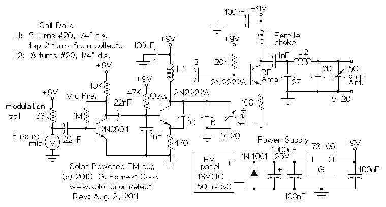
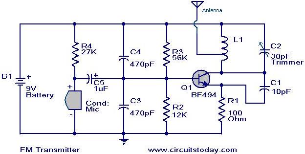
Here are some utility circuits for use with the Ramsey FM10a, and other small FM stereo transmitter kits. This information may be helpful for setting up a micro powered FM radio station. The FM10a and similar kits tend to...
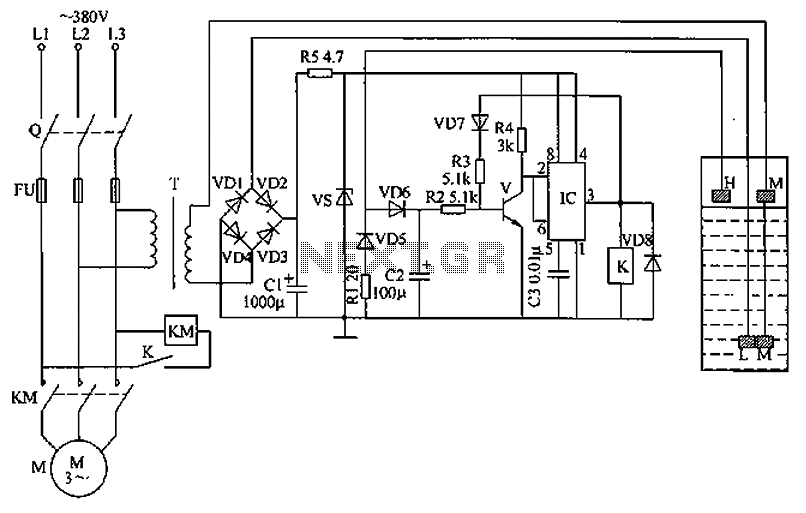
The circuit functions as a liquid level automatic controller, comprising a power circuit, a level detection circuit, and a control execution circuit. The power circuit includes a knife switch (Q), fuse (FU), power transformer (T), rectifier diodes (VD1 to...
Safety devices like fuses provide protection against excess current, but do nothing for transients and short duration spikes of high voltage on the power supply lines. This circuit uses the "crowbar" method and provides fast protection against transient voltage...
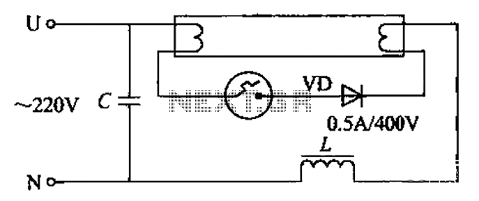
By incorporating a second pull tube into the circuit during the starter ionization phase, the positive half-cycle diode conduction results in an approximate DC current flow. This current is rectified, and due to the small ballast impedance, the instantaneous...