
Over Voltage Protection

The described circuit employs a thyristor-based crowbar protection mechanism to safeguard sensitive electronic components from transient voltage spikes. The primary function of this circuit is to provide rapid response to over-voltage conditions, which can occur due to various factors such as inductive load switching, lightning strikes, or other electrical disturbances.
In the circuit, a Zener diode is utilized to establish a predetermined voltage threshold. When the power supply voltage exceeds this threshold, the Zener diode conducts, causing a voltage rise across a connected 4.7k ohm resistor. This voltage increase triggers the thyristor, which is designed to activate within microseconds, effectively creating a low-resistance path to ground. This rapid action results in the power supply rails being short-circuited, thereby diverting excess voltage away from sensitive components.
The duration of the short circuit is critically limited to a few milliseconds, allowing for the immediate reduction of voltage before the primary fuse in the circuit blows. This delay is crucial as it mitigates the risk of damage to components that may not withstand high transient voltages. The fuse serves as a secondary line of defense, ensuring that the circuit is ultimately protected from sustained overcurrent conditions that could arise if the thyristor remains conductive for an extended period.
Simulation tools, such as TINA, can be used to analyze the circuit's performance under transient conditions, providing visual representations of voltage and current waveforms. This simulation can help in understanding the effectiveness of the crowbar circuit in real-world scenarios, illustrating the rapid response time and the effectiveness of the protective measures implemented in the design. Overall, this circuit is an essential component in applications where transient voltage spikes pose a significant risk to electronic devices.Safety devices like fuses provide protection against excess current, but do nothing for transients and short duration spikes of high voltahe on the power supply lines.This circuit uses the "crowbar" method and provides fast protection against transient voltage spikes, transients that could cause damage to sensitive components. The thyristor will trigger in a few microseconds. This is over 1000 times faster than an ordinary quick blow fuse. If the output voltage exceeds the limit set by the zener, then it will conduct. The voltage across the 4.7k resistor will rise, the thyristor switches on and the power rails are short circuited.
The duration of the short circuit will be only a few milliseconds before the fuse blows. In these few milliseconds the voltage will be greatly reduced. Below is a simulated transient plot, using the TINA program. In the circuit above, and the graph the tr 🔗 External reference
Related Circuits

Power demand in portable designs can require, in specific applications, more than 1 A. A method involves paralleling two DC to DC converters on the same load instead of using a single higher current converter with a lower switching...
The LM1036 is a DC-controlled circuit designed for tone adjustment (bass/treble), volume control, and balance. It is suitable for use in car radios, televisions, and audio systems. The circuit also incorporates loudness compensation. The LM1036 integrates several functionalities essential for...
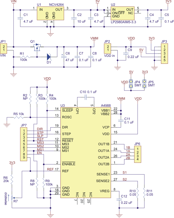
Best 1183 - A4988 Stepper Motor Driver Carrier with Voltage Regulator in Robot Italy. The A4988 stepper motor driver carrier with voltage regulators is a breakout board for Allegro's easy-to-use A4988 microstepping bipolar stepper motor driver. The board has...
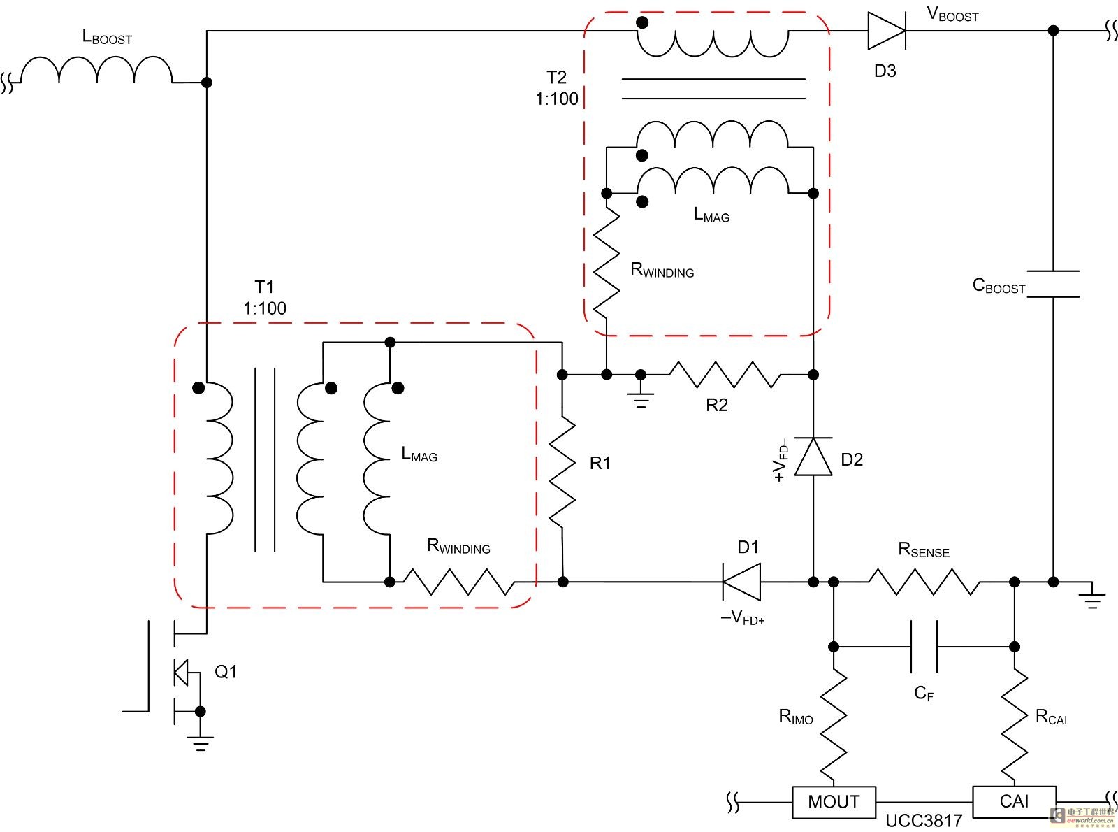
Mode control of the average current (CMC) is necessary to regulate the overall waveform of electric current during the rebuilding cycle. This text recommends selecting specific parameters related to the voltage transformer and outlines steps for designing a circuit...
The circuit in the diagram generates a negative voltage without using integrated circuits. It utilizes five n-p-n transistors driven by an approximately 1 kHz TTL clock. When the clock input is high, transistors T1 and T2 connect capacitor C1...
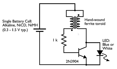
A transformer with two input leads and three output leads was used. An LED was connected to two of the output leads, and when a dead AA battery was connected to the input leads, the LED blinked for a...