
Sixteenth street control circuit composed of the second decoding circuit diagram

The Sixteenth Street control circuit serves as a vital component in a larger system, allowing for precise control of multiple outputs through a decoding mechanism. The second decoding output control circuit decodes a binary input into one of sixteen possible outputs. Each output is connected to a bistable circuit, which is implemented using dual D flip-flops (CD4013). This configuration enables each output to maintain its state until a triggering event occurs.
The CD4013 dual D flip-flop is a versatile and widely used component in digital electronics. It features two independent D flip-flops, each capable of storing one bit of information. The flip-flops are triggered by a clock signal, allowing for synchronous operation. In this circuit, the flip-flops are utilized to create a bistable operation, where each output can toggle between two stable states (on or off) based on the input signals.
Connected to each output terminal of the bistable circuit is a DC relay. The relay serves as an electromechanical switch that can control higher power devices or circuits. When the bistable circuit changes state, it activates the corresponding relay, allowing for the control of external loads such as lights, motors, or other electronic devices. The use of relays enhances the versatility of the control circuit, enabling it to interface with a variety of applications.
Overall, the design of the Sixteenth Street control circuit emphasizes reliability and functionality, leveraging the capabilities of CD4013 flip-flops and DC relays to achieve efficient control over multiple outputs in a systematic manner.Sixteenth street control circuit composed of the second decoding output control circuit. Connect an bistable circuit that composed of dual D flip-flop CD4013 to every output terminal of the sixteen decoding. Connect a DC relay on each output terminals of bistable circuit.. 🔗 External reference
Related Circuits
Utilizes a barium titanate transducer as a microphone, tuned with a 20 mH coil to generate peaks at control frequencies of 38.5 kHz and 41.5 kHz. A balanced discriminator detects the two ultrasonic tones. A frequency shift in the...

The provided information pertains to a detector circuit designed for multiplication. This circuit functions as a single-sideband amplitude modulation (SSB AM) signal detector, utilizing its principles to demodulate the received single-sideband signal and recover the transmitted signal. It employs...
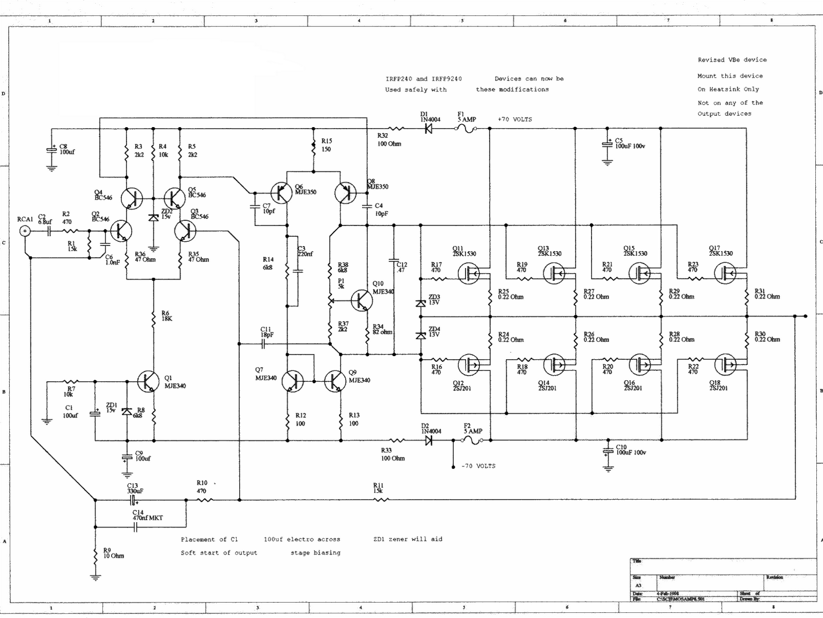
This is a simple LED-powered audio amplifier circuit utilizing a MOSFET amplifier with the TL071C operational amplifier. It can deliver up to 45 W into an 8-ohm load. The circuit incorporates the MOSFETs IRFP240 and IRFP9240, which are recommended...
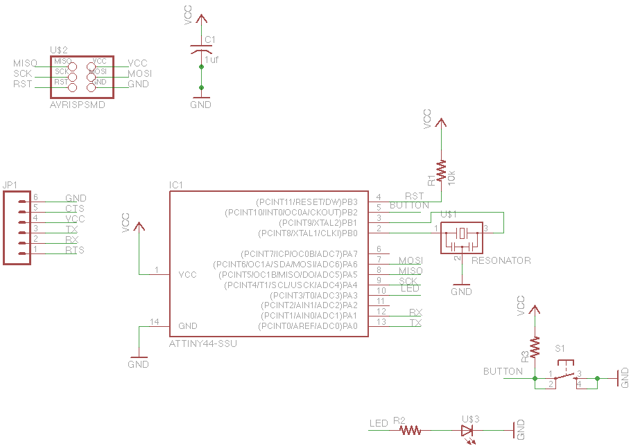
For this week's assignment, a chip design was provided, and the task was to incorporate a button and an LED (light-emitting diode). The objective was to fabricate the chip and program it to interact with the light and button....

The circuit operates as follows: each morning, light enters the silicon photocell, generating a force that causes transistor VT1 to conduct. As a result, capacitor C charges, leading to an increase in voltage. This rising voltage causes the emitter...
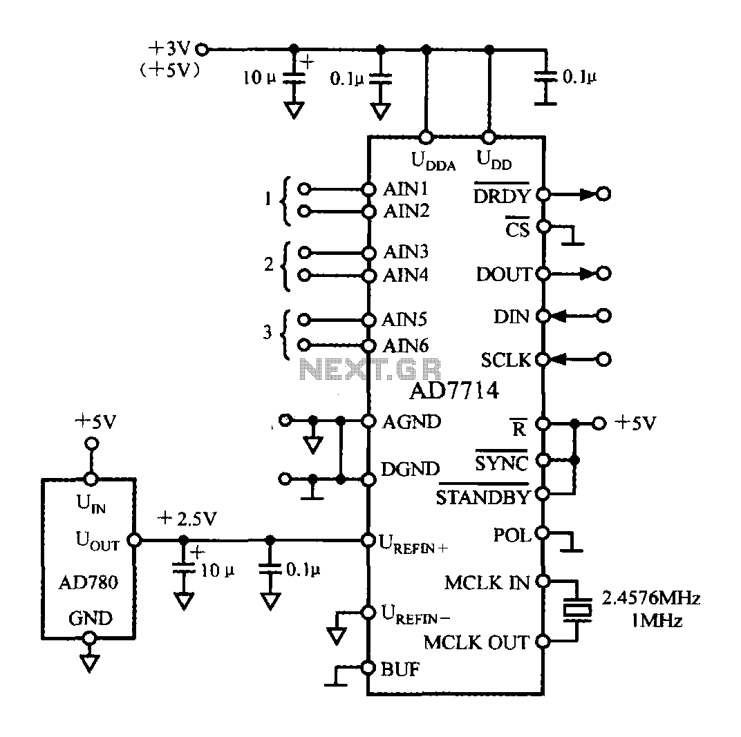
The typical application circuit for the AD7714 is illustrated in the accompanying figure. The UDD and UDDA terminals of the AD7714 can be connected to either a +3V or +5V power supply. The analog inputs are arranged as three...