
Sleep Mode Circuit Circuit

The HA7210 oscillator is a versatile component that generates clock signals, which are essential for timing operations within the circuit. It operates by providing a precise frequency output, which can be adjusted based on external components connected to it. The integration of the IOL7642 quad CMOS op amp enhances the circuit's functionality by allowing for multiple amplification stages and signal conditioning processes. This combination is particularly effective in low-power applications where energy conservation is crucial.
The sleep-mode control circuit is designed to minimize power consumption when the system is not in active use. The logic high applied to the Reset input serves as a manual trigger for entering sleep mode, effectively halting operations to save energy. Alternatively, the RC timer provides an automatic reset capability, allowing the circuit to transition into sleep mode after a predetermined period of inactivity. The RC time constant can be adjusted by changing the resistor and capacitor values, providing flexibility in the design.
Upon receiving a signal from a microphone or sensor, the circuit exits sleep mode and resumes normal operation. This feature is particularly useful in applications such as motion detection, environmental monitoring, or any system that requires periodic activation based on external stimuli. The overall design ensures that the system remains responsive while maintaining energy efficiency, making it suitable for battery-powered devices or applications where power supply is limited. The HA7210 oscillator 10 combines with an IOL7642 quad CMOS op amp to produce a sleep-mode control circuit. The circuit is put into the sleep mode with a logic high applied to the Reset input or with an RC timer for automatic reset.
The system is awakened by a signal from the microphone/sensor.
Related Circuits
This is a very simple project using a printed circuit board and 8 components. It will flash an ordinary 3mm or 5mm (1/8" or 1/4") LED at a rate of about one flash per second. This circuit works on...

This weblog discusses electronic circuit schematics, PCB design, DIY kits, and electronic project diagrams. The circuit diagram presented is for a magnetic proximity switch, which has numerous applications across various fields. The circuit utilizes a magnetic reed switch (S1)...
This circuit serves as a dependable alternative to thermally-activated switches designed for flashing Christmas tree lamps. The arrangement consisting of Q1, Q2, and associated resistors activates the silicon-controlled rectifier (SCR). The timing function is determined by resistors R1, R2,...
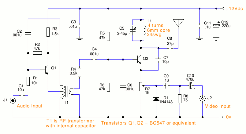
This is a small TV transmitter circuit that transmits in VHF, utilizing negative sound modulation and PAL video modulation. It is suitable for countries that use the B and G system. T1 refers to a type of transformer. The...

The objective is to demonstrate that the electrical field energy produced by a well-designed Tesla coil transmitter can be detected by a sensitive, well-tuned Tesla coil receiver placed at distances exceeding a few wavelengths. The current investigations involve scaled-down...

A circuit diagram controls the timing based on the input line state. When the input line is high, the 4016 CMOS analog switches select the timing of a 1.5 megohm resistor (Rt1) to produce negative output pulses at a...