
Unsteady programmable circuit diagram

The described circuit utilizes a 4016 CMOS analog switch, which is a quad analog switch that allows for the selection of different resistive timing components based on the state of an input control signal. The circuit operates by routing the timing resistor through the analog switch to produce desired output frequencies.
When the input signal is high, the switch connects to a 1.5 megohm resistor (Rt1). This resistor, in conjunction with the associated capacitive components, determines the timing characteristics that yield a negative output pulse at a frequency of 100 Hz. The negative pulse indicates that the output signal transitions from a high state to a low state, producing a square wave with a specific frequency determined by the RC time constant.
In the alternate state, when the input signal is low, CMOS switch S2 opens, and the circuit selects a 1.2 megohm resistor (Rt2). This configuration alters the RC timing characteristics, resulting in an output frequency of 120 Hz. The choice of resistors directly affects the frequency of the output signal, illustrating the flexibility and utility of the analog switch in adapting the circuit's response based on input conditions.
The output pulses generated can be used for various applications such as timing circuits, frequency modulation, or as a clock signal for digital circuits. The precise control over the output frequency via resistor selection allows for fine-tuning in applications requiring specific timing intervals. The design ensures low power consumption typical of CMOS technology while providing reliable switching characteristics.A circuit diagram of the control when the input line is high time, 4016CMOS analog switches will choose the timing of 1.5 megohm resistor Rt1, to produce a negative 100Hz to ou tput pulses. When the input is low, CMOS switch S2 opens, select the 1.2 megohm resistor Rt2 timing to generate the output of 120Hz.
Related Circuits
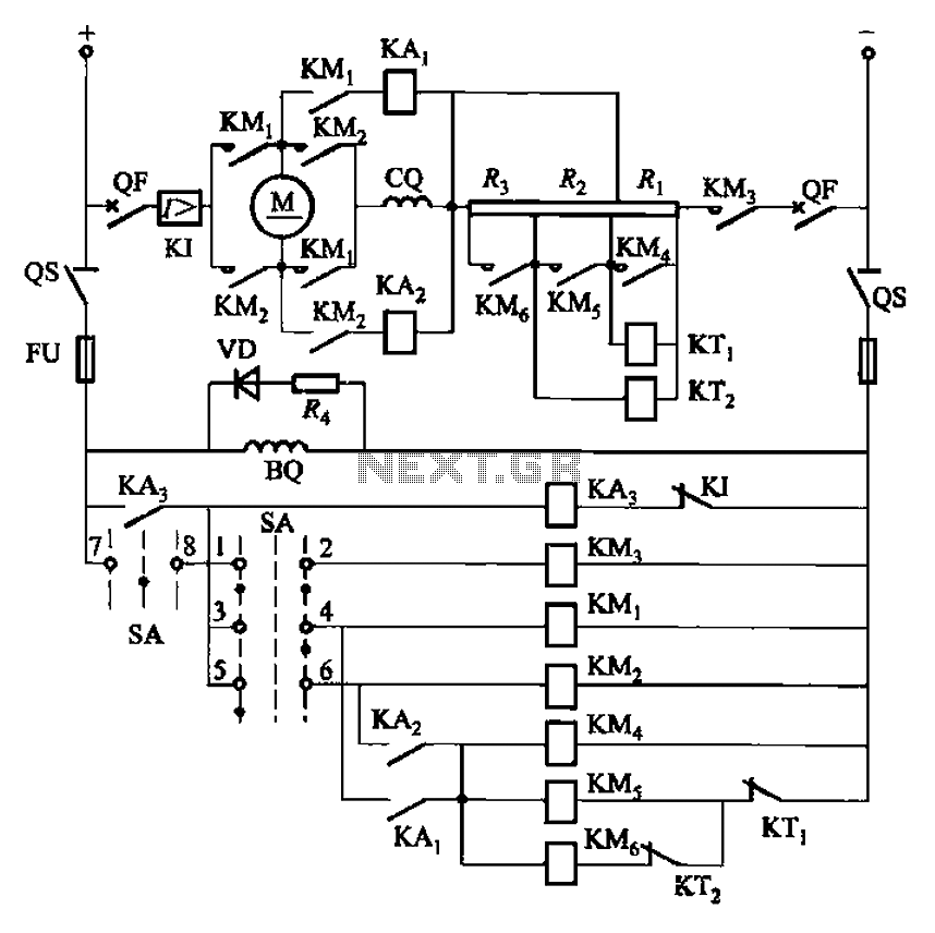
The circuit depicted in Figure 3-201 includes two starting resistors, with one controlled by a time relay. A master switch (SA) is utilized to manage the motor's reversing operation. The circuit incorporates a reverse braking mechanism, which is automatically...
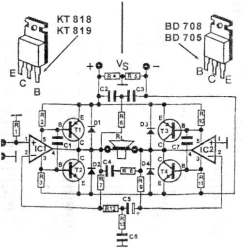
This audio amplifier circuit provides up to 200 W of high-quality output for loudspeakers with impedances ranging from 4 to 16 ohms. The operating voltage is between 24 and 36 V, with a maximum current of 5 A. The audio...
This device is designed to be a simple, inexpensive comparator intended for use in a solar cell power supply setup where a quick indication of "too low" or "just right" voltage is needed. The circuit consists of one 5V...
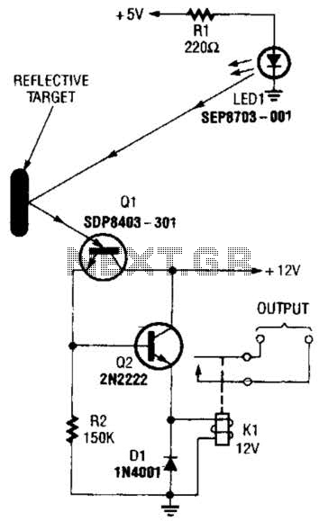
A reflector isolator detects the presence of an object by bouncing light off of it. This technique is useful in circuits that detect when an object is close enough to the sensor. A reflector isolator is a type of optical...
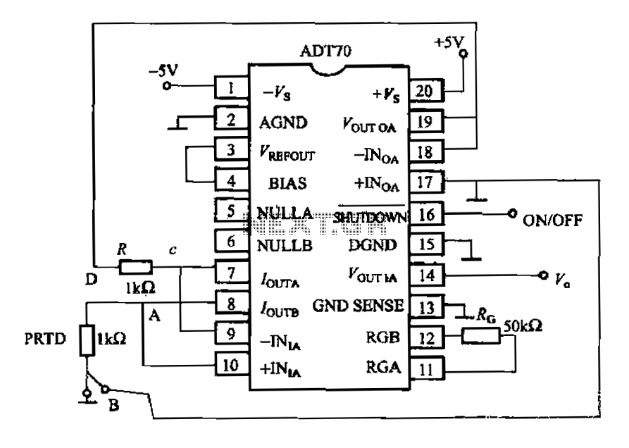
The AD170 basic electrical parameters include a temperature coefficient of 25 ppm/°C and a temperature measurement accuracy of ±1°C, with a maximum temperature range of -200°C to +100°C. The power supply required is +5V or -5V, and the operating...
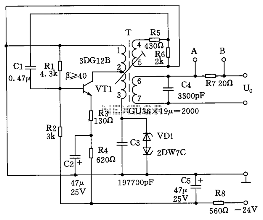
The circuit depicted in the figure allows for the selection of optimal operating conditions and a suitable allocation of the temperature coefficient for the resonant circuit components. The resonance occurs at both ends of the circuit. Additionally, the exchange...